
Why Your LS Catch Can Is Filling So Quickly—and What to Test First
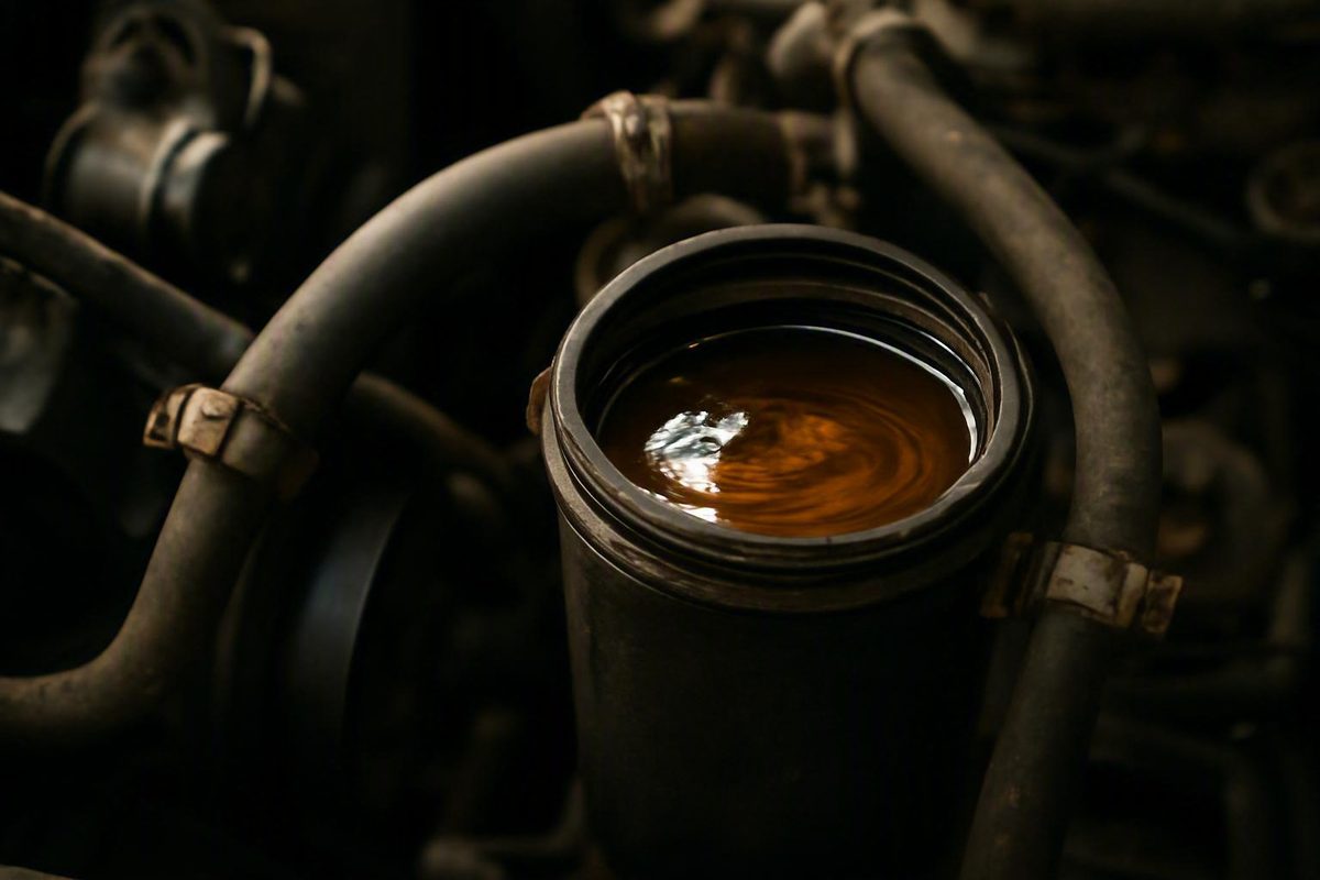
Wrong routing, a blocked fresh-air path, poor baffling, condensation and fuel-contaminated vapor can all contribute without proving bad rings.
An LS oil catch can that fills quickly is reporting a symptom, not delivering a diagnosis. The liquid may be mostly engine oil, condensed water, fuel-contaminated fluid, or an emulsion. Even when the contents are predominantly oil, possible causes include direct oil pickup, ineffective baffling, incorrect PCV routing, inadequate ventilation capacity, excessive blow-by, or overlapping faults.
There is no evidence-based universal collection rate for every LS engine. Catch-can capacity and construction vary, as do LS generations, valley and valve covers, PCV arrangements, engine condition, climate, mileage, modifications, fuel, boost, and driving load. Diagnose the problem in order:
- Measure what the can collects.
- Identify the likely fluid.
- Verify the installation and complete ventilation path.
- Find the branch supplying the liquid.
- Evaluate ventilation performance under the conditions that produce the symptom.
- Test engine condition if routing, pickup, and separation do not explain it.
First determine whether the filling rate represents an urgent problem
A can filling faster than another owner’s does not establish a fault by itself. Unverified owner reports range from modest accumulation over several thousand miles to a full can during a short track session, but the engines, plumbing, can sizes, weather, and measurement methods differ too much to create a diagnostic threshold. For example, one rebuilt Z06 owner reported a full can over 1,400 miles, while modified track-engine owners described cans filling during several qualifying laps or a 20-minute session (CorvetteForum rebuild report; Corvette track-use reports).
Begin with when the behavior started:
- Immediately after installing the can: Prioritize port direction, hose routing, the fresh-air path, application compatibility, and separator construction.
- After changing valve covers, the valley cover, intake plumbing, forced-induction hardware, or PCV components: Reinspect every altered part and connection.
- Mainly in cold weather or after short trips: Condensation may contribute substantially to the measured volume.
- Only during sustained RPM, track use, or boost: The system may be encountering oil pickup, separation, or ventilation-demand problems that do not appear during gentle driving.
- Suddenly after a stable pattern: A new restriction, damaged component, tune-related problem, or internal mechanical fault deserves greater attention.
Avoid hard use while investigating if rapid filling accompanies a falling crankcase oil level, heavy exhaust smoke, misfires, reduced performance, new oil leaks, unusually heavy crankcase vapor, abnormal measured pressure, or a sudden change from prior behavior. These combined symptoms are more informative than catch-can volume alone.
Empty the can before it reaches capacity and check it frequently during diagnosis. Do not assume that every full can blocks PCV flow or sends all its contents into the intake. A winter LS1 owner reported a manifold-connected can full of water-and-oil mixture, but the thread did not document a confirmed blockage or engine failure (LS1TECH cold-weather report).
Before further testing, verify the engine-oil level on level ground using the applicable vehicle or engine procedure. If the can has collected a visibly large amount of oil and the crankcase is low, restore the level only to the specified mark. Record how much oil is added so that an important diagnostic clue is not lost.
Measure the accumulation and identify what the can is collecting
“Full after one drive” is less useful than a measured volume connected to distance, engine hours, weather, and load. Establish a repeatable collection log:
- Empty the can and remove enough old residue that it will not dominate the next sample.
- Check and record the crankcase oil level.
- Drain the next catch into a clear graduated container.
- Record the volume in milliliters or fluid ounces.
- Record miles driven or engine hours, rather than elapsed days alone.
- Let the sample settle in a sealed, clearly labeled container suitable for the collected automotive fluid.
- Repeat under comparable operating conditions.
Include the following details:
- Date, ambient temperature, and relevant wet or humid conditions
- Trip length and number of cold starts
- Short-trip use versus fully warmed operation
- Street, towing, autocross, drag, or road-course use
- Sustained engine speed and approximate duration
- Boost operation, if applicable
- Fuel type and recent calibration changes
- Oil grade and recent oil-level adjustments
- Catch-can volume
- Crankcase oil-level change
- Smoke, misfires, leaks, or performance changes
- Date the behavior began
- PCV, intake, valve-cover, valley-cover, or engine work performed beforehand
Compare the collected volume with crankcase oil loss.
Appearance provides clues, not proof:
- Dark and viscous: Consistent with a high oil fraction, but not conclusive.
- Milky tan or gray: Consistent with an oil-and-water emulsion; color alone cannot distinguish ordinary condensation from coolant contamination.
- A separated watery layer: Indicates that water may be present but does not identify its source.
- Unusually thin fluid or a fuel odor: Raises the possibility of fuel contamination but cannot establish the amount or cause.
- Distinct layers after settling: Helps show that the sample is a mixture but is not laboratory identification.
A cold metal can can condense water-rich crankcase vapor, particularly when repeated short trips do not keep the engine and plumbing fully warm. In one Silverado report, the original poster found different liquids in the PCV-side and clean-side cans after short operation and later observed less accumulation during warmer driving. The liquid was not laboratory tested, and the thread did not establish a final diagnosis (Silverado owner report).
Fuel contamination requires separate investigation. The original poster in a modified 416 stroker discussion reported approximately 350–400 mL of thin catch-can liquid per 100 km, believed it contained substantial E85, and also described a rich break-in tune and heavy vapor. Those observations apply to that highly modified supercharged combination and do not prove fuel contamination in another engine merely because its sample smells sharp or feels thin (Chevy SS forced-induction report).
Do not diagnose a coolant leak from milky residue alone. Monitor for unexplained coolant loss and use an appropriate cooling-system or combustion-gas test if other evidence warrants it. Investigate suspected fuel dilution through injector operation, calibration, misfire history, engine-oil condition, and oil analysis where appropriate—not by smell alone.
Understand the three main fault categories
A practical troubleshooting model divides rapid accumulation into three categories.
1. Liquid-oil pickup or poor separation
The engine-side ventilation outlet may be exposed to liquid oil or dense mist, while its baffle fails to keep that oil away from the outlet. The catch can itself may also provide too little flow redirection or separation area.
This can produce a substantial quantity of oil without proving severe ring blow-by. Manifold vacuum may simply be drawing from an oil-rich location through ineffective baffling.
2. Inadequate crankcase-ventilation flow
The complete system includes the fresh-air inlet, crankcase outlet, hoses, fittings, PCV restriction or valve, separator, and destination connection. A restriction in any part may prevent the arrangement from handling the engine’s actual gas flow, particularly at sustained RPM or under boost.
Possible signs include pressure that rises under load, oil leaks, mist from a breather, or oil overwhelming the separator.
3. Excessive combustion-gas leakage into the crankcase
Blow-by is combustion gas passing the piston rings into the crankcase. Increased blow-by raises the gas and suspended mist that the ventilation system must process. Poor ring sealing or piston damage can therefore overwhelm a system that previously appeared adequate.
These categories can overlap. A worn or damaged engine may exceed the capacity of marginal plumbing, while a mechanically serviceable engine may feed liquid oil directly into an unbaffled valve-cover or valley outlet.
An engine that runs well is not automatically cleared. The rebuilt Z06 owner cited earlier reported substantial oil consumption and a full can despite good performance and no obvious smoke. Reused pistons and uncertainty about ring replacement raised concern, but the discussion supplied no completed compression, leak-down, crankcase-pressure, or teardown findings. The case therefore illustrates an unresolved diagnostic question—not confirmed ring failure.
Likewise, little visible vapor at an open oil-fill cap does not rule out a ventilation or sealing problem.
Use onset as evidence. Fast filling that begins with a new installation puts routing, port orientation, compatibility, pickup location, and separator construction high on the list. An abrupt increase after stable operation makes a new restriction, failed component, damaged baffle, calibration problem, or internal fault more plausible.
Verify catch-can direction, PCV routing, and the fresh-air path
Do not copy another vehicle’s diagram merely because both engines are called LS engines. Before tracing the system, identify:
- LS generation and engine code
- Donor vehicle or original application, if the engine was swapped
- Valley-cover design
- Valve-cover design and vent locations
- Fixed orifice, PCV valve, or other flow-control arrangement
- Dirty-side crankcase outlet
- Filtered or metered fresh-air inlet
- Intake-manifold vacuum connection
- Pre-throttle or pre-compressor connection, where applicable
- Catch-can make, model, intended application, and marked flow direction
- Supercharger, turbocharger, camshaft, displacement, intake, or cover changes
Obtain the correct configuration from the service information for the engine or donor vehicle, the engine builder’s documentation, and the instructions for every installed separator, valve, check device, and forced-induction component. If parts from several applications have been combined and no documented configuration exists, have the completed system reviewed by a technician or builder familiar with that combination.
Verify the can manufacturer’s inlet and outlet markings. Direction can matter when the intended inlet faces a baffle, diffuser, mesh, or chamber that the reverse path bypasses. Treat a generic, unmarked, or application-mismatched can with particular caution.
One LS3 owner reported that a generic, unmarked can patterned after a different application filled most of its container within a few hundred miles. Participants proposed routing, direction, valley baffling, and blow-by, but the supplied discussion contained no completed test or confirmed cause (Camaro5 LS3 discussion).
Trace the complete path:
- Locate the dirty-side crankcase outlet.
- Follow it to the intended can inlet.
- Follow the can outlet to its documented vacuum or evacuation source.
- Locate the filtered or metered fresh-air inlet.
- Identify any valves or restrictions and confirm their intended direction.
- Determine which path operates during manifold vacuum and, on a boosted engine, which path operates when the manifold is pressurized.
Inspect for:
- Reversed can ports
- The wrong vacuum source
- A blocked fresh-air connection
- An open breather added to a system intended to remain closed
- Kinked, collapsed, softened, or leaking hoses
- Excessive hose length or sharp bends
- Restrictive adapters
- Fittings with internal passages much smaller than the attached hose
- Incorrectly installed or malfunctioning flow-control devices
Port reversal is an essential check, not a guaranteed diagnosis. In one unresolved naturally aspirated 383 LS1 report, reversing the can lines did not stop the can from filling during a short drive. Participants also questioned the valve-cover baffling and fresh-air arrangement (LS1TECH routing discussion).
It must also retain the documented evacuation and fresh-air strategy for each operating state. Because superchargers, turbochargers, covers, valves, and intake arrangements differ, there is no responsible universal diagram for every boosted LS.
Do not improvise by capping required vents while the engine is running. Likewise, do not randomly disconnect branches in an attempt to “see what happens.” Instead, compare the completed routing with the relevant documentation and evaluate pressure with suitable equipment.
Inspect vent baffling, catch-can construction, and the oil-entry location
A ventilation outlet exposed to direct oil splash can feed the can even when crankcase pressure is not extreme. The engine-side baffle should allow vapor flow while requiring oil droplets to change direction and drain back rather than travel directly into the hose.
Inspect the outlet area for:
- A missing, displaced, cracked, or incorrectly installed baffle
- A fitting positioned above a concentrated oil stream
- An aftermarket fitting installed without adequate splash separation
- Modified valve covers with little internal separation
- A valley cover that does not match the assumed PCV arrangement
- Assembly or sealing faults that create a direct oil path
- Debris, sealant, or damage affecting the intended passage or drainback area
A component vendor identifies LS Gen III and Gen IV valley areas and locations near pushrod oil flow as potentially vulnerable to oil carryover. It recommends redirecting flow at both the engine outlet and inside the separator. This is a useful inspection hypothesis, but it is vendor guidance rather than independent comparative testing (Motion Raceworks baffling guide).
Inspect the can itself. Determine whether it contains actual flow redirection, separation media, or multiple chambers rather than an empty space between two fittings. Check whether the outlet sits above the expected liquid level and whether the installation orientation matches the manufacturer’s instructions. External size alone does not establish separation performance.
Do not assume that either the valley or a valve cover is always the dominant source. In the track-use discussion cited earlier, individual owners reported much greater collection from valve-cover branches than from valley-connected cans. One described a valve-cover can becoming half full during a track day while the valley can remained empty; another reported markedly different quantities among the driver-side, fresh-air-side, and valley branches. These uncontrolled observations do not establish a universal pattern, but they show why the source should be inspected rather than assumed.
For a correctly configured system:
- Inspect each hose for fresh internal oil wetness.
- Note which fitting or branch becomes wet first.
- Examine the baffle directly behind each outlet.
- Inspect the corresponding hose immediately after the operating condition that triggers the problem.
- If the application’s documented design permits separate collection from multiple branches, use properly configured separators without eliminating required ventilation paths.
- Compare only runs performed under reasonably similar conditions.
Multiple cans can help identify or contain liquid from separate branches, but they are not automatically a repair. They may leave direct pickup, deficient baffling, restricted plumbing, or excessive pressure unchanged.
Inspect downstream components as access permits. Look for fresh oil at the throttle body, intake-manifold connection, supercharger inlet, compressor inlet, and accessible charge plumbing. The pattern can help determine whether oil is passing through the separator or entering through another ventilation connection.
A wet breather filter or oil escaping from a can indicates that the system’s separation or operating capacity needs attention. An absorbent cover may conceal the discharge but does not identify or correct its source.
Account for track use, boost, engine build, and cold-weather operation
A setup that appears acceptable during commuting may behave differently during sustained load. Higher crankcase gas flow, prolonged RPM, boost, and rapid oil movement can expose pickup, separation, or restriction problems that do not appear during ordinary driving.
Track reports illustrate what can occur without defining a normal threshold. Modified LS stroker owners have reported cans filling in approximately 15–20 minutes or within several qualifying laps. Their engine builds, can sizes, baffles, oil levels, plumbing, and measurement methods differed, so the reports establish only that severe accumulation can be operating-condition dependent—not that a particular rate is normal for a stroker.
When the symptom appears mainly on track, investigate:
- Whether a particular outlet becomes freshly oil-wet
- Which branch supplies most of the collected liquid
- Whether hoses soften or collapse under vacuum
- Whether a breather becomes saturated
- Whether measured crankcase pressure changes with RPM and load
- Whether the oil level was set by the correct procedure
- Whether collection occurs consistently during the same type of session
- Whether the can’s installed orientation matches its instructions
Strokers appear frequently in extreme owner reports, but the evidence does not isolate stroke or displacement from ring fit, piston design, bore finish, output, RPM, oil control, baffling, and track use. “They all do that” is not a diagnosis.
For a fresh or rebuilt engine, document the build rather than declaring the collection normal break-in behavior:
- Were the rings replaced?
- Were ring fit and orientation documented?
- Were reused pistons inspected and measured?
- What bore preparation and finish were used?
- Was piston and cylinder condition verified?
- Was the initial calibration unusually rich?
- Did misfires occur during early operation?
- Is the collection rate improving, stable, or worsening?
- Did the problem begin immediately or after a particular high-load event?
A boosted engine adds both routing and capacity questions. Establish what evacuates the crankcase when manifold vacuum is available, what operates when the manifold is pressurized, and how filtered or metered air enters. Confirm that each valve or check device is installed in its documented direction.
For an E85 engine or one operating unusually rich, include fuel-contaminated vapor and crankcase fuel dilution among the conditions to investigate. Fuel type alone does not establish the cause; injector problems, cold-start enrichment, repeated short operation, misfires, calibration, and ring sealing may all require evaluation.
Cold-weather accumulation has a different diagnostic pattern. A cold-mounted can may collect more liquid because it condenses more water-rich vapor, even when mechanical blow-by has not increased. Compare winter and warm-weather results, trip length, and crankcase oil loss before treating a seasonal increase as evidence of ring damage.
Changing to thicker oil is not an established cure. In the cited track discussion, one modified-engine owner reported that changing from 10W-30 to 20W-50 made collection worse. That single report does not establish how another engine will respond, but it does show why viscosity should not be selected merely to mask catch-can accumulation. Follow the oil requirements applicable to the engine, operating temperature, clearances, and builder or manufacturer guidance.
Test engine condition when routing and baffling do not explain it
Escalate to engine-condition testing when:
- Accumulation increases suddenly
- Crankcase oil level falls quickly
- Exhaust smoke appears
- Misfires or reduced performance develop
- Crankcase vapor becomes unusually heavy
- Oil leaks appear at multiple locations
- Measured pressure or vacuum differs abnormally from the applicable specification or established baseline
- Rapid filling continues despite verified routing and effective baffling
- One branch supplies excessive oil without an identifiable pickup fault
Begin with a compression test across all cylinders using a consistent procedure. Record every cylinder rather than testing only one associated with a misfire.
Follow with a warm leak-down test across all cylinders. Record:
- Engine temperature
- Test equipment and pressure
- Reading for each cylinder
- Crank position and how the engine was secured
- Where leakage is heard or observed
Do not apply a universal percentage without accounting for equipment, temperature, procedure, and engine configuration. If the engine builder, service information, or test-equipment manufacturer supplies a procedure or comparison standard, use it.
Measure crankcase pressure or vacuum under the operating condition that produces the symptom. An idle-only reading may not reproduce a problem seen during boost or sustained RPM. Use equipment rated for the expected environment and follow an applicable service or component procedure.
Interpret the result against one of the following:
- An applicable OEM, component-manufacturer, or engine-builder specification
- A documented prior baseline from the same engine and configuration
- A comparison collected by a qualified diagnostic shop using a repeatable procedure
Additional checks include:
- Verify PCV flow and the operation of any fixed orifice, valve, or check device according to its documentation.
- Compare spark plugs for oil fouling, fuel fouling, or a cylinder-specific anomaly.
- Inspect cylinders and piston crowns with a borescope.
- Look for scoring, unusual deposits, visible piston damage, or one cylinder that differs from the others.
- Inspect intake and boost plumbing for fresh oil.
- Review misfire data, fuel trims, and calibration history where relevant.
- Note whether oil leakage appears after the same high-load conditions that fill the can.
Visible vapor from an open oil-fill cap is not a substitute for these tests. Opening the cap changes the circuit, and visual observation cannot quantify pressure or identify the responsible cylinder.
Combined evidence carries more weight than can volume. In the supercharged 416 report, the original poster later described heavy blow-by smoke and leak-down readings above 20% in most cylinders, including 28% in one. Those reported findings increased concern about sealing, but the test conditions and final teardown were not documented, so they did not prove the exact internal failure.
A broken ring land, damaged piston, poor ring fit, unsuitable bore preparation, or worn rings remain possibilities to confirm—not conclusions justified by a full catch can. Internal repair should be based on converging evidence from oil loss, pressure measurement, cylinder comparison, leakage location, plug condition, borescope findings, or teardown inspection.
Choose the repair from the confirmed fault and verify the result
Match the repair to the evidence.
If the installation is wrong, correct the documented inlet and outlet direction and restore the intended PCV routing. Reestablish the required filtered or metered fresh-air path. Replace kinked, collapsed, leaking, oil-damaged, or unnecessarily restrictive hoses and fittings.
If the engine outlet has a direct oil path, repair or replace the deficient baffle or use a pickup arrangement documented for the application. If the separator lacks meaningful internal flow redirection or does not work in its required orientation, replace it with a suitable design compatible with the ventilation layout.
If testing shows inadequate evacuation, evaluate the entire system rather than buying only a larger reservoir. Hoses, fittings, flow-control devices, the separator, and the destination connection must suit the engine’s actual ventilation demand. The evidence does not support one universal hose size or can volume for every stock, stroked, track-driven, or boosted LS.
Do not make a larger or second can the automatic first response. Extra storage may delay overflow while leaving direct oil pickup, incorrect routing, ineffective baffling, or a mechanical problem unchanged. Separate cans may be useful when independently evaluated branches require collection, but they should not replace diagnosis.
Closed PCV and vent-to-atmosphere arrangements are application-dependent. Atmospheric venting changes where crankcase vapor and oil mist are discharged and may create odor or residue. It can also conflict with a system designed around metered air. Before changing the arrangement, review the vehicle, engine, induction, and component documentation applicable to the build.
Internal engine repair becomes appropriate when testing supports it. If compression comparison, warm leak-down, crankcase-pressure behavior, plug inspection, borescope findings, and oil consumption converge on poor sealing or piston damage, repair the demonstrated mechanical fault. Do not disassemble an otherwise well-running engine solely because its catch can filled faster than another owner’s.
After any repair:
- Empty the can.
- Set and record the crankcase oil level.
- Drive under comparable weather, trip length, load, RPM, and boost conditions.
- Measure the liquid with the same graduated container.
- Compare its appearance and settled layers.
- Recheck the crankcase oil level.
- Inspect for intake oil, smoke, leaks, breather wetness, and abnormal pressure behavior.
If correcting a baffle reduces collection while oil consumption, smoke, misfires, or poor cylinder-test results remain, continue the mechanical diagnosis.
The decision path is: identify the fluid, verify the installation, locate the oil-entry branch, evaluate ventilation under actual use, measure engine condition, repair the demonstrated fault, and retest.
Frequently asked questions
How much oil in an LS catch can is too much?
There is no universal ounces-per-mile or milliliters-per-hour limit for every LS engine. Can capacity, PCV configuration, engine condition, weather, modifications, and operating load vary too widely.
Treat the result as more concerning when it is a sudden increase, approaches the can’s working capacity before routine checks, corresponds with falling crankcase oil level, or accompanies smoke, misfires, leaks, heavy vapor, reduced performance, or abnormal pressure behavior. Drain and measure it before comparing it with previous operation under similar conditions.
Does a catch can filling fast mean the piston rings are bad?
No. Poorly sealing rings can increase blow-by and oil mist, but rapid filling can also result from direct liquid-oil pickup, ineffective vent or can baffling, incorrect routing, a blocked fresh-air path, restrictive plumbing, condensation, or fuel-contaminated vapor.
An internal fault becomes more plausible when the increase is sudden or is supported by oil loss, smoke, misfires, abnormal measured crankcase pressure, cylinder-to-cylinder compression differences, leak-down findings, plug anomalies, or borescope evidence.
Why does my LS catch can fill with milky liquid in cold weather?
The can may be condensing water-rich crankcase vapor. A cold metal separator and repeated short trips can encourage water to collect and mix with a small quantity of oil, producing a tan or milky emulsion.
Milky appearance does not prove ordinary condensation. Track coolant level, crankcase oil loss, weather, and trip length, and use appropriate testing if unexplained coolant loss or other cooling-system symptoms appear.
Can incorrect catch-can routing pull oil into the can?
Yes. Reversed directional ports, an incorrect vacuum connection, a blocked fresh-air branch, or a connection to a poorly baffled oil-rich outlet can increase oil pickup. The can may also be ineffective when connected backward if its internal separator is directional.
Verify the exact engine’s ventilation layout and the can manufacturer’s inlet and outlet instructions. Do not assume that an unmarked generic can follows another product’s port arrangement.
Should I vent my LS catch can to atmosphere?
Not as a universal fix. Atmospheric venting may change where vapor and oil mist go without correcting direct oil pickup, poor baffling, excessive pressure, or internal damage. It may also create odor, residue, or incompatibility with a metered-air arrangement.
Choose the configuration from the engine, induction system, component instructions, and intended operating environment. Whichever arrangement is used, verify it by measuring collection and crankcase-pressure behavior under the conditions that previously produced the symptom.
The bottom line
Drain and measure the contents first. Compare the collected volume with crankcase oil loss, and document temperature, trip length, RPM, load, and boost. Verify the exact LS PCV layout and catch-can direction, inspect both the engine-side pickup and separator baffling, and identify which vent supplies the liquid.
If the increase began suddenly or accompanies oil loss, smoke, misfires, heavy vapor, leaks, reduced performance, or abnormal pressure behavior, avoid hard use and proceed to measured crankcase-pressure, compression, warm leak-down, spark-plug, borescope, and intake checks. Repair what the evidence demonstrates, then repeat the same collection log under comparable conditions rather than relying on a universal fill-rate rule.