
Which O2 Sensor Is Which—and What the Data Actually Means
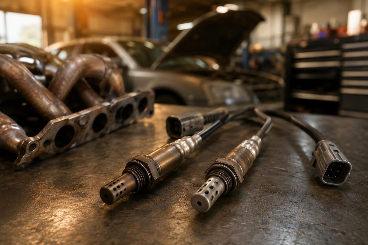
Upstream vs. downstream oxygen sensors at a glance
The practical difference between an upstream and downstream oxygen sensor is not simply “front versus rear.” The upstream sensor is mainly a fuel-control input, while the downstream sensor is mainly a catalyst-monitoring input.
| Comparison | Upstream oxygen sensor | Downstream oxygen sensor |
|---|---|---|
| Typical location | Before the catalytic converter, often in or near the exhaust manifold | After the catalytic converter or at its outlet |
| Primary function | Reports engine-out exhaust oxygen so the control module can make closed-loop fuel corrections | Reports exhaust conditions after the converter, primarily for catalyst and emissions-system monitoring |
| Common scan-tool label | Sensor 1, such as B1S1 or B2S1 | Sensor 2, such as B1S2 or B2S2 |
| Typical conventional narrowband behavior | Changes rapidly between lean and rich indications once warm and in closed loop | Usually less active than the upstream signal when the converter is functioning effectively |
| Likely effect of a genuine fault | May disrupt fuel control and contribute to drivability, fuel-economy, or emissions problems | May turn on the warning light or prevent reliable catalyst monitoring, sometimes without obvious drivability symptoms |
| Replacement considerations | Sensor technology, calibration, heater, connector, wire length, bank, and exact position matter | May look similar to the front sensor but should not be assumed interchangeable |
The normal exhaust path is:
Engine / exhaust manifold
          │
          ▼
  Upstream O2 sensor
       Sensor 1
          │
          ▼
  Catalytic converter
          │
          ▼
 Downstream O2 sensor
       Sensor 2
          │
          ▼
       Tailpipe
“Upstream” normally means the sensor is before the catalytic converter. “Downstream” normally means it is after the converter. The upstream sensor sees exhaust as it leaves the engine and supplies oxygen-related feedback that the powertrain control module can use to adjust injector operation and fuel trims. The rear sensor observes exhaust after the converter and primarily helps the control module evaluate catalyst and emissions-system operation. This distinction is also described in CarParts.com’s comparison of upstream and downstream sensors.
These are typical conventions, not a complete map for every vehicle. An inline engine may have one upstream and one downstream sensor. A V-type engine may have separate sensors and converters for each cylinder bank.
Physical location can therefore be less obvious than the diagram suggests. Identify the sensor from the code definition and actual exhaust layout—not simply by choosing whichever sensor is easiest to see.
How to decode Bank 1, Bank 2, Sensor 1, and Sensor 2
Oxygen-sensor labels combine a cylinder bank with a position in the exhaust stream:
- Bank 1 is the cylinder bank containing cylinder 1.
- Bank 2 is the other bank on an engine with two cylinder banks.
- Sensor 1 generally identifies the upstream sensor for that bank.
- Sensor 2 generally identifies the first downstream sensor for that bank.
- Sensor 3, where used, identifies an additional position farther along the exhaust path.
Accordingly:
- Bank 1 Sensor 1, or B1S1: normally the upstream sensor serving the bank containing cylinder 1.
- Bank 1 Sensor 2, or B1S2: normally the first downstream sensor on that bank.
- Bank 2 Sensor 1, or B2S1: normally the upstream sensor serving the other cylinder bank.
- Bank 2 Sensor 2, or B2S2: normally the corresponding downstream sensor on Bank 2.
These position conventions—and the possibility of an additional Sensor 3—are described in the upstream-versus-downstream position guide.
A simplified two-bank system might look like this:
Bank 1 — contains cylinder 1

Bank 1 cylinders ──► B1S1 ──► Converter 1 ──► B1S2 ──┐
                                                      │
                                                      ├──► Tailpipe
Bank 2 cylinders ──► B2S1 ──► Converter 2 ──► B2S2 ──┘

Bank 2 — other cylinder bank
That drawing is only an example. Some vehicles join both banks before a shared converter. Others use separate close-coupled converters plus an underfloor converter. The code may consequently refer to another sensor position or a manufacturer-specific exhaust arrangement.
Do not assume Bank 1 is always on the driver side or always on the passenger side. Establish the physical bank from manufacturer service information, a cylinder-numbering diagram, an underhood label, or another vehicle-specific source.
The number and placement of downstream sensors depend on the converter and emissions configuration.
Parts-catalog terminology may also differ from scan-tool terminology. A catalog might say “front,” “rear,” “before catalyst,” “after catalyst,” “left,” or “right” instead of B1S1 or B1S2. Denso’s oxygen-sensor position guide explains that a position note supplies only a general location and must be combined with the vehicle-information notes.
Treat the bank-and-sensor label as an address, not a diagnosis. It identifies the circuit or exhaust position the control module is discussing; it does not establish that the sensor installed there has failed.
Why the upstream sensor controls fuel differently from the downstream sensor
During applicable closed-loop operation, the control module uses upstream exhaust-oxygen information to determine whether combustion is trending rich or lean relative to its target. It can then change commanded fueling and record corrections through short- and long-term fuel trims.
That makes the upstream sensor primarily a control sensor. If the sensor, heater, wiring, or related circuit genuinely fails, the control module may lose accurate or timely mixture feedback. Depending on the vehicle and fault, the result can include poor fuel control, reduced fuel economy, hesitation, rough operation, elevated emissions, or a warning light.
Those symptoms are not specific to an oxygen sensor. Vacuum leaks, incorrect fuel pressure, injector faults, ignition faults, airflow-measurement errors, exhaust leaks, and mechanical problems can produce similar evidence.
The downstream sensor is primarily a diagnostic monitor. It allows the control module to observe exhaust after the converter and compare post-catalyst behavior with upstream conditions. A rear-sensor circuit fault may therefore turn on the malfunction indicator or prevent a catalyst monitor from running even when the vehicle appears to drive normally.
“Primarily” is important. The downstream or diagnostic sensors only monitor the exhaust leaving the catalytic converter Troubleshooting Oxygen Sensors - Walker Products. For general diagnosis, however, the front sensor is the main mixture-feedback input and the rear sensor is the main catalyst-monitoring input.
Oxygen-sensor-related codes generally fall into four useful categories:
-
Sensor-signal circuit faults These concern signal range, activity, response, or electrical continuity. Possible causes include the sensing element, wiring, terminals, grounds, connectors, and the exhaust conditions being reported.
-
Heater-circuit faults Heated sensors use an electrical heater to reach and maintain their operating state. A heater code directs diagnosis toward the heater circuit, but it does not automatically prove that the entire sensor assembly is defective.
-
Reported rich or lean conditions The sensor may be accurately reporting a mixture or exhaust-oxygen problem originating elsewhere. A lean report is not synonymous with a bad sensor, and a high signal is not automatic proof of failure.
-
Catalyst-efficiency faults These concern the relationship between pre-catalyst and post-catalyst information. Diagnosis must account for converter behavior, both sensor circuits, exhaust integrity, engine operation, and the conditions under which the monitor ran.
Walker Products’ oxygen-sensor troubleshooting guide emphasizes that an OBD-II code alone does not establish sensor failure: a functioning sensor may simply be reporting a lean condition created elsewhere.
The diagnostic question is therefore not only, “Which sensor is named?” It is also, “Is that sensor producing an incorrect report, or is it correctly reporting another fault?”
What upstream and downstream live data should look like
Live data is useful only when the test conditions and displayed parameters are understood. Before interpreting a graph, confirm that:
- The engine is warm.
- The system is in the relevant closed-loop operating state.
- The correct bank and sensor have been selected.
- The displayed parameter represents voltage, current, lambda, equivalence ratio, or another known value.
- The upstream and downstream traces are being compared under the same speed and load.
- Misfires, temperature faults, or supply-voltage problems are not invalidating the comparison.
Conventional narrowband upstream behavior
A warm, conventional narrowband zirconia upstream sensor normally moves rapidly between lean and rich indications as the control module corrects fueling. Approximately 0.1 volt on the lean side to 0.9 volt on the rich side is a common illustration, not a universal specification. Vehicle-specific limits and response criteria take priority, and the conventional range does not apply to wideband air-fuel sensors. See the ASE-reviewed conventional oxygen-sensor testing overview for the applicable narrowband context.
Conceptually, an active narrowband upstream trace might look like this:
Voltage
High / / / /\
/ / / / \
Low ___/ \/ \__/ \/ \___
      --------------------------------► Time
             Upstream switching
The important characteristic is responsive movement between lean and rich indications—not a requirement that every peak and valley reach exactly the same voltage.
Typical downstream behavior
When the converter is functioning effectively and conditions are suitable, a conventional downstream trace is generally less active than the upstream trace:
Voltage
High
          ________        ________
/ \______/
Low  ___/
      --------------------------------► Time
           Comparatively smooth rear trace
There is no single healthy downstream voltage for every vehicle. Generic sources describe different typical values because the trace is affected by sensor technology, catalyst condition and loading, engine load, exhaust temperature, fuel-cut events, and manufacturer strategy. Relative activity and vehicle-specific pass/fail criteria are more useful than one universal voltage snapshot.
Fixed high or fixed low
A signal that remains high or low requires investigation, but it does not identify the failed part by itself:
Fixed high:  ───────────────────────────

Fixed low:   ___________________________
             --------------------------► Time
A fixed high indication may reflect a genuine rich condition, contamination, a circuit fault, or a sensor that is no longer responding. A fixed low indication may reflect a genuine lean condition, an exhaust leak admitting outside oxygen, a misfire leaving excess oxygen in the exhaust, an open circuit, or a sensor fault.
Check fuel trims and related engine data before interpreting the line. A low signal accompanied by strong positive fuel correction presents different evidence from a low signal with normal trims and a failed vehicle-specific response test.
Sluggish response
A sluggish conventional upstream sensor may transition too slowly for the mixture changes being commanded:
Voltage
High /────── /────
/ /
Low __________/ \________/
      --------------------------------► Time
                Slow transitions
That pattern can support a response-time concern, but first consider whether the mixture itself is changing slowly, the exhaust is not sufficiently warm, the test conditions are unsuitable, the sensor is contaminated, the circuit is compromised, or the scan tool has a slow refresh rate. The correct response threshold is vehicle-specific.
Similar upstream and downstream traces
If the post-catalyst trace closely resembles the pre-catalyst trace, the converter may not be buffering upstream oxygen fluctuations as expected:
Upstream: / / / / / /\
\/ \/ \/ \/ \/ \/

Downstream: / / / / / /\
\/ \/ \/ \/ \/ \/
             --------------------------► Time
This pattern supports further catalyst-system investigation, but it does not independently prove converter failure. Exhaust leaks, unresolved rich or lean operation, misfires, incorrect sensor identification, rear-sensor circuit faults, and testing before the catalyst reaches suitable operating conditions can all affect the comparison.
Use waveform shape as evidence within a diagnosis, not as a standalone verdict.
Identify narrowband, wideband, or air-fuel-ratio technology before testing
The familiar rich-to-lean switching-voltage test mainly applies to conventional narrowband zirconia sensors. It should not be generalized to every component that a scan tool or catalog calls an O2 sensor.
Newer systems may use a wideband or air-fuel-ratio sensor, especially in the upstream position.
Applying a generic narrowband multimeter test to an air-fuel-ratio sensor can produce meaningless results. Select the test only after identifying the installed technology from:
- Manufacturer service information
- The wiring diagram and connector pinout
- Scan-data parameter names and units
- The exact original-equipment or replacement part description
- The VIN-specific emissions configuration
- The manufacturer’s diagnostic chart for the stored code
A live-data-capable scan tool is usually the better starting point because it can display several related facts together:
- Stored, pending, permanent, and related codes
- Freeze-frame conditions
- Open-loop or closed-loop status
- Coolant temperature
- Short- and long-term fuel trims
- Misfire data, where supported
- Upstream and downstream sensor traces
- Commanded or measured air-fuel information
That context helps distinguish a faulty report from a functioning sensor reporting a real engine or exhaust problem. A meter may show one electrical value, but it does not show whether the engine is adding fuel, whether a cylinder is misfiring, or whether the system was in closed loop when the value was captured.
Direct probing remains useful when the prescribed diagnostic path requires power, ground, signal-integrity, or heater-resistance checks. Follow the correct wiring diagram, terminal identification, and vehicle-specific limits.
Use particular care around a running engine and hot exhaust. Follow the vehicle’s service procedure, secure the vehicle as directed, keep clear of moving components, and do not probe or disconnect a circuit unless the specified test permits it. General oxygen-sensor multimeter safety guidance also warns about hot exhaust parts and electrical-test precautions.
A diagnosis-first workflow for oxygen-sensor codes
Use the code as the beginning of the test plan—not as a parts order.
1. Record all diagnostic information
Before clearing anything, record:
- Stored and pending codes
- Permanent codes, if available
- Freeze-frame data
- Readiness-monitor status
- Fuel trims
- Misfire information
- Coolant temperature and operating status
- The exact bank-and-sensor description
Related codes can change the direction of diagnosis. A sensor code accompanied by misfire, fuel-pressure, airflow, or system-voltage codes requires broader investigation than an isolated sensor-circuit code.
2. Verify the bank and sensor position
Confirm that the code refers to the sensor you intend to inspect. Determine:
- Which bank contains cylinder 1
- Whether the code names Sensor 1, Sensor 2, or Sensor 3
- Which converter the sensor is before or after
- Whether the scan-tool wording matches the manufacturer’s definition
For example, P0135 may refer to a Bank 1 Sensor 1 heater-circuit fault, while P0136 may refer to a Bank 1 Sensor 2 circuit fault; the exact definitions must still be checked for the vehicle. These examples are documented in the conventional oxygen-sensor diagnostic guide.
P0141 is another example commonly associated with a downstream oxygen-sensor heater circuit, but shortened generic-reader wording may omit useful details. Verify the manufacturer’s definition rather than diagnosing from the code number alone, as illustrated in this OBD live-data testing guide.
3. Inspect the wiring and connector
Follow the harness from the sensor as far as practical. Look for:
- Melted or heat-damaged insulation
- Chafing against shields, brackets, or drivetrain components
- Oil, coolant, water, or road contamination in the connector
- Bent, spread, pushed-back, or corroded terminals
- A connector that is not fully locked
- Damage from previous exhaust or engine work
- Poor grounds or unauthorized wiring repairs
Inspect the sensor body and nearby exhaust as well. Physical damage and deposits can provide clues, but appearance alone does not establish electrical performance.
4. Confirm the operating conditions
Check whether the engine reaches its expected operating temperature and whether the control system enters closed loop when required. Evaluate sensor activity only under the conditions specified by the diagnostic procedure.
A cold engine, inactive heater, fuel-cut event, unstable idle, active misfire, or recently cleared adaptive memory may produce misleading data. Do not compare traces captured under different loads and treat the difference as a component verdict.
5. Review live data as a system
Graph the relevant upstream and downstream parameters together. Add fuel trims, engine speed, load, coolant temperature, and closed-loop status if the scan tool permits.
Ask:
- Does the upstream sensor respond when mixture conditions change?
- Do fuel trims agree with the reported rich or lean condition?
- Is the downstream trace less active under comparable conditions?
- Are both banks behaving similarly?
- Is one bank abnormal while shared engine inputs appear normal?
- Are misfire counters increasing?
- Does the fault occur only during idle, warm-up, cruise, or load?
Comparing banks can be useful on a two-bank engine. A problem isolated to one bank can direct attention toward bank-specific causes, while similar behavior on both banks can suggest a shared input or operating condition. Neither pattern is an absolute diagnosis.
6. Follow the path that matches the code category
For a sensor-signal circuit code: inspect the connector, signal wiring, grounds, terminal tension, contamination, and any applicable reference or bias circuit. Determine whether the sensor responds when exhaust conditions change and whether the unusual value is an accurate report of a real mixture problem.
For a heater-circuit code: verify the applicable fuse or supply, control path, ground, connector, and wiring. Measure heater resistance or current only according to the correct terminal identification and specifications. An internally open heater is possible, but so are broken wires, poor grounds, damaged terminals, and control-side faults.
For a lean reading or lean code: investigate unmetered intake air, vacuum leaks, exhaust leaks ahead of the sensor, insufficient fuel delivery, airflow-measurement errors, injector restrictions or control faults, and misfires. An upstream exhaust leak may admit outside oxygen, while a misfiring cylinder may leave excess oxygen in the exhaust. Either can create a lean report that sensor replacement will not correct.
For a rich reading or rich code: determine whether the sensor is accurately reporting excess fuel or reduced oxygen. Consider fuel delivery, injector leakage, airflow information, purge operation where applicable, ignition quality, and other vehicle-specific causes. A persistently high narrowband indication alone does not prove that the sensor is shorted or contaminated.
For a catalyst-efficiency code: verify engine operation, fuel control, exhaust integrity, both sensor circuits, and the required monitor conditions before judging the converter.
7. Perform the vehicle-specific component test
After related causes have been addressed, follow the manufacturer’s sensor-response, circuit, heater, or catalyst test. The prescribed process may involve controlled operating conditions, scan-tool commands, electrical checks, or comparison with known limits.
Replace an oxygen sensor only when inspection, circuit testing, response testing, and the applicable specifications support that conclusion. A code naming an oxygen-sensor position proves that the control module detected a problem associated with that circuit or condition—not that the sensing element itself has failed.
Bad downstream sensor or failing catalytic converter?
This distinction can be difficult because the downstream sensor reports conditions after the converter. Its data reflects both the rear sensor’s operation and the oxygen-storage behavior of the catalyst system ahead of it.
The downstream narrowband trace should therefore generally be less active than the front trace. If the rear waveform begins to resemble the upstream waveform, catalyst efficiency becomes a valid concern.
That resemblance is not a conclusive converter test. Before condemning the converter, account for:
- Exhaust leaks
- Unresolved rich or lean operation
- Active or intermittent misfires
- Front- or rear-sensor wiring faults
- Heater faults
- Sensor contamination
- Insufficient engine or catalyst temperature
- Fuel-cut and transient operating conditions
- Incorrect bank or sensor identification
- Misinterpretation of the installed sensor technology
Replacing the rear sensor will not correct a catalyst-efficiency code if the sensor is accurately reporting poor catalyst oxygen-storage behavior. Conversely, replacing the converter is premature if the rear-sensor circuit, exhaust integrity, fuel control, and engine operation have not been verified.
Compare the evidence under the same conditions:
- Confirm closed-loop status and suitable temperature.
- Graph the upstream and downstream parameters together.
- Review short- and long-term fuel trims.
- Check misfire data.
- Look for rich, lean, heater, and circuit codes.
- Inspect for exhaust leaks before and near the converter.
- Confirm that the rear sensor responds plausibly rather than merely appearing steady.
- Apply the manufacturer’s catalyst and sensor pass/fail procedure.
A perfectly flat rear line is not automatically good. It may represent an inactive sensor, electrical fault, unsuitable test conditions, or a misunderstood scan parameter. A moving rear line is not automatically bad because load changes, fuel-control activity, and catalyst conditions affect what the sensor sees.
No single downstream voltage or generic waveform threshold applies to every system. Use manufacturer service information for the final sensor and converter decision.
How to order the correct upstream or downstream sensor
Do not assume upstream and downstream sensors are interchangeable simply because their threads or bodies look alike. Differences may include:
- Connector shape and keying
- Terminal arrangement
- Harness length
- Protective sleeve and routing clips
- Heater characteristics
- Sensor technology
- Calibration
- Specified bank and exhaust position
This does not mean the positions can never share a part number. Some applications may specify the same component in more than one location. Exact vehicle fitment and part-number data—not appearance or a generic label—determine interchangeability.
Use this ordering checklist:
- Model year
- Make and model
- Engine displacement and engine code
- Emissions configuration or certification
- VIN application
- Production date
- Country or plant of assembly, where specified
- Chassis or serial-number break, where specified
- Transmission, drivetrain, or weight classification, where specified
- Bank number
- Sensor number
- Before- or after-converter position
- Left or right position, if the catalog uses it
- Connector and lead configuration
- Original or superseding part number
Check the emissions-system label and every catalog vehicle-information note. Fitment may depend on production date, assembly location, emissions standard, transmission code, or chassis criteria—not merely model year and engine. Denso’s fitment guidance specifically warns that position notation gives only a general location.
Do not order from a listing that says only “upstream,” “downstream,” “left,” or “right” unless the full application details also match. Catalog directions and scan-tool bank designations are separate identification systems.
If the old part is accessible, compare the connector, lead length, routing clips, sensor body, and part marking, but do not rely on appearance alone. A previously installed universal or incorrect sensor can make that comparison misleading.
Vehicle service information and detailed catalog fitment data override generic location conventions. Confirm the VIN application, engine, emissions package, exact bank and position, connector, and part number before purchase.
Frequently asked questions
Is Sensor 1 upstream and Sensor 2 downstream?
Generally, yes. Sensor 1 normally identifies the upstream sensor for the specified bank, while Sensor 2 normally identifies the first sensor downstream of that bank’s converter.
B1S1 is therefore usually the upstream sensor on the bank containing cylinder 1, and B1S2 is usually the corresponding downstream sensor. Verify the actual exhaust layout because systems with several converters may use an additional position such as Sensor 3.
Can upstream and downstream oxygen sensors use the same part?
Sometimes, but only when the exact application specifies the same part number for both positions. Do not assume interchangeability from physical appearance.
The parts may differ in technology, calibration, heater characteristics, connector, terminal arrangement, lead length, and routing hardware. Match the VIN application, engine, emissions configuration, bank, sensor position, connector, and catalog notes.
Does an oxygen-sensor code mean the sensor is bad?
No. It means the control module detected a circuit fault, heater fault, response problem, rich or lean condition, or catalyst-related condition associated with that part of the system.
The sensor may be defective, but it may also be correctly reporting a vacuum leak, exhaust leak, misfire, fuel-delivery fault, airflow-measurement error, rich condition, or weak converter. Wiring, connectors, power supplies, grounds, and heater circuits must also be considered.
Should I test an oxygen sensor with a scan tool or a multimeter?
Start with a live-data-capable scan tool in most cases. It can show codes, freeze-frame conditions, closed-loop status, fuel trims, misfire information, and both sensor traces together. That context helps distinguish a bad report from a functioning sensor reporting another problem.
Use a multimeter or other electrical equipment when the vehicle-specific procedure calls for circuit, supply, ground, or heater testing. First identify whether the sensor is narrowband, wideband, or an air-fuel-ratio design. Do not apply a conventional narrowband voltage test to every sensor technology.
How many oxygen sensors does a vehicle have?
There is no universal number. Sensor count depends on the engine layout, number of cylinder banks, converter arrangement, model year, and emissions configuration.
An inline-engine vehicle may have one upstream and one downstream sensor. A two-bank engine commonly has an upstream sensor for each bank and may have one or more downstream sensors. Systems with several converters may use additional monitoring positions.
Final diagnosis-before-parts takeaway
Identify the bank and sensor position, determine the installed sensor technology, inspect the wiring and exhaust system, and review warm-engine live data alongside fuel trims, misfire information, and related codes. Then apply the vehicle-specific circuit, response, heater, or catalyst test.
The practical distinction remains straightforward: the upstream sensor is mainly a fuel-control input, while the downstream sensor is mainly a catalyst monitor. Neither a trouble code nor one waveform is a final diagnosis.