
Test the Regulator Before You Replace It
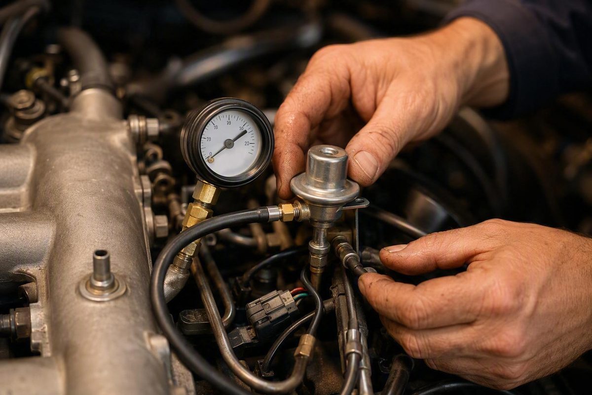
Hard starting, rough idle, hesitation, fuel odor, rich or lean codes, and abnormal fuel pressure can all accompany a faulty fuel pressure regulator. None of those clues proves the regulator is bad. Pumps, filters, injectors, fuel lines, return restrictions, pressure sensors, wiring, and power-supply problems can produce similar results.
A reliable diagnosis starts by identifying the fuel-system design and obtaining the factory procedure for the exact year, make, model, engine, and test condition. You can then measure baseline pressure, check regulator response where applicable, and monitor pressure retention after shutdown.
This article covers conventional low-pressure gasoline fuel-injection systems.
Quick answer: the checks that establish whether a regulator is working
The shortest reliable diagnostic sequence is:
- Identify the system. Determine whether the vehicle has an external vacuum-referenced regulator, an in-tank or returnless regulator, or electronically controlled fuel pressure.
- Find the exact specifications. Use service information for the precise vehicle, engine, fuel-system design, and specified test condition.
- Inspect before opening the system. Check for damaged hoses, loose fittings, visible leakage, restricted lines, and vacuum or electrical problems.
- Inspect an external regulator’s vacuum connection. With the engine off and cool, check the hose and regulator nipple. Liquid gasoline there is strong evidence of a ruptured diaphragm.
- Connect the correct gauge. Use a fuel-injection-rated gauge at the manufacturer-specified test point or with the approved adapter.
- Record prime and running pressure. Compare both readings with the applicable factory specifications, not a generic pressure range.
- Test regulator response where applicable. A working vacuum-referenced regulator should produce a predictable pressure change when vacuum is removed or applied. The required change is vehicle-specific.
- Check pressure after shutdown. Record residual pressure for the interval specified by the manufacturer.
- Interpret the complete pattern. Determine whether the regulator—or a pump, filter, injector, line, return path, sensor, wiring, or power-supply fault—best explains the repeatable results.
On a confirmed external vacuum-operated gasoline regulator, liquid fuel in the vacuum hose or nipple is one of the strongest indications of diaphragm failure. A gauge test should still be evaluated against the vehicle’s factory specifications rather than a universal target (Quantum Fuel Systems’ regulator-testing guide).
Most other findings require further diagnosis. Low pressure does not prove the regulator is stuck open. High pressure does not prove it is stuck closed. An unstable gauge or rapid pressure loss after shutdown identifies a condition, not necessarily the component responsible.
The central rule is: confirm the pressure pattern, then exclude plausible alternatives before buying a regulator.
Identify the fuel-system design before choosing a test
The first question is not “What pressure should this vehicle have?” It is “What type of fuel system am I testing?” A test suitable for a rail-mounted vacuum regulator may be irrelevant or unsafe on another design.
Use the service manual or fuel-system diagram to identify:
- The regulator and its location
- The approved pressure-test connection
- The return line, if fitted
- The fuel-pressure sensor, if fitted
- The pump-control components
- The applicable pressure specifications and test conditions
External vacuum-referenced regulator
This design commonly has a mechanical regulator associated with the fuel rail, a small vacuum connection, and a return path to the tank. Intake-manifold pressure acts on the regulator diaphragm, allowing fuel pressure to change predictably with vacuum.
Do not identify the regulator by appearance alone. A damper, check valve, pressure sensor, or unrelated vacuum device can be mistaken for it. Confirm the component and hose routing in vehicle-specific service information.
Once identified, an external vacuum regulator can commonly be evaluated through:
- Inspection of the vacuum hose and regulator nipple
- Mechanical pressure-gauge testing
- A vacuum-disconnect response test
- A hand-vacuum-pump test, where approved
- A residual-pressure test after shutdown
If the vehicle does not have a confirmed external regulator vacuum hose, the vacuum-hose test does not apply.
In-tank or returnless regulator
A returnless system may regulate pressure in the tank or pump module instead of returning excess fuel from the rail. It may have no external return line and no vacuum-operated regulator on the engine.
Testing therefore focuses on:
- Mechanical pressure at the approved test point
- Prime, running, and specified load behavior
- Residual-pressure retention
- Pump voltage and ground
- Commanded pump operation
- Fuel-pressure sensor data, when fitted
- Manufacturer-directed in-tank module tests
Some systems require a specified in-line adapter because they lack a rail-mounted test valve. The absence of a visible regulator does not mean pressure is unregulated.
Electronically monitored or controlled pressure
Some systems use a pressure sensor and vary pump operation electronically. Others combine mechanical regulation with electronic monitoring. Diagnosis may require scan data and electrical tests in addition to a mechanical gauge.
Service information should identify:
- The sensor location
- Commanded and actual pressure data
- The pump-control module, relay, or driver circuit
- Required power, ground, signal, and reference-voltage checks
- The approved method for comparing scan data with mechanical pressure
A scan-tool reading is not automatic proof of physical rail pressure. If scan data and a correctly connected mechanical gauge disagree significantly, verify the gauge setup and investigate the sensor and its circuit before replacing a pump or regulator.
Direct injection and diesel systems
Stop and obtain a system-specific professional procedure if the engine uses gasoline direct injection or high-pressure common-rail diesel.
Use this routing decision:
- Confirmed external vacuum regulator: Follow the vacuum-regulator inspection and gauge procedure.
- Returnless or electronically controlled system: Use mechanical pressure, scan data, electrical checks, and the applicable module procedure.
- Gasoline direct injection or high-pressure common-rail diesel: Stop and use the manufacturer’s high-pressure procedure or refer the work to a qualified professional.
Tools, specifications, and fuel-system safety
Fuel-pressure testing involves a system containing pressurized, flammable liquid. Preparation and the correct equipment are essential.
Core equipment
Gather:
- Factory service information for the exact vehicle and engine
- A fuel-pressure gauge rated for the system
- The specified fuel-compatible adapters
- Safety glasses
- Fuel-resistant gloves
- Shop rags or absorbent material
- A suitable way to contain released fuel
- An optional hand-operated vacuum pump for an applicable regulator
- A scan tool and electrical test equipment when electronic monitoring or control must be evaluated
Do not select a gauge merely because its threads appear to fit. Its gauge, hose, seals, and adapters must be compatible with gasoline and rated for the system.
Before testing, find the manufacturer’s:
- Approved gauge connection point
- Pressure-relief procedure
- Required operating conditions
- Prime and running pressure targets
- Expected vacuum or electronic-command response
- Residual-pressure limit and test interval
- Required pump-activation method
A vehicle without a Schrader valve requires its specified in-line or rail adapter. Do not improvise with unverified tees, hoses, clamps, or fittings. General fuel-pressure guidance likewise calls for a purpose-built tester connected at the rail valve or another approved point (O’Reilly Auto Parts’ fuel-pressure testing guide).
Work-area precautions
Work with a cool engine in a well-ventilated location. Eliminate smoking, flames, sparks, and other ignition sources. Keep absorbent material ready, contain released fuel, and relieve residual pressure exactly as the manufacturer directs before loosening a connection. The correct relief method varies by vehicle (Quantum Fuel Systems’ symptom and testing guide).
Stop rather than proceed if:
- The correct test connection cannot be identified
- A fitting is cracked, corroded, rounded, or otherwise damaged
- A hose, rail, or fitting is visibly leaking
- The gauge or adapter lacks a suitable rating
- The connection would require improvised hardware
- The system is an unfamiliar high-pressure design
- Fuel is already present in the regulator vacuum hose or entering the intake
Do not treat pump noise or a visible squirt of fuel as proof of adequate supply. A pump may run but still fail to produce the specified pressure or sufficient fuel volume under demand (FixKick’s application-specific fuel-pressure guide).
Avoid routine shortcuts that pinch or block the return line. Restricting the return can produce abnormally high pressure and load the pump, while a change in engine operation still does not identify why baseline pressure was wrong. Use return-line restriction only when the exact service procedure expressly requires it and provides the method and limits.
Compressed-air bench testing is also not a universal regulator test. Application-specific discussions describe it, but it can introduce leakage, contamination, or component damage. Use it only when an approved component procedure specifically calls for it.
Inspect an external vacuum-operated regulator before using the gauge
A careful inspection may reveal a decisive fault before the engine needs to run.
With the engine off and cool, inspect:
- The regulator body and mounting point
- Fuel fittings and seals
- The vacuum hose and intake connection
- Nearby supply and return lines
- Clips, clamps, and retainers
- Areas below the rail for staining or wetness
- The return path for kinks, crushing, heat damage, or incorrect routing
A damaged vacuum hose can prevent correct regulator response even when the regulator itself works. A restricted return line can imitate a regulator that cannot open. A loose fitting can cause pressure loss unrelated to internal regulation.
Check the vacuum hose for liquid fuel
Remove the regulator vacuum hose only as directed by the service procedure. With the engine off, inspect the hose interior and regulator nipple.
Liquid gasoline at this connection is strong evidence of a perforated diaphragm on a confirmed external vacuum-operated gasoline regulator. A perforation can allow pressurized fuel to enter the vacuum side, after which intake vacuum may draw it through the hose into the manifold. That can contribute to a rich condition and hard starting (Premier Auto Trade’s regulator fault-finding article).
A gasoline odor without visible liquid is less conclusive. Inspect further rather than condemning the regulator from smell alone.
If raw fuel is entering the vacuum hose or intake, stop unnecessary engine operation. Verify the component and source of the fuel, repair the fault, and follow the vehicle procedure for addressing the resulting over-fueled condition.
Check whether the diaphragm holds vacuum
If the design and service procedure permit:
- Leave the engine off.
- Disconnect the regulator’s vacuum hose as specified.
- Connect a hand-operated vacuum pump to the regulator nipple.
- Apply the prescribed vacuum.
- Observe whether the regulator holds it for the specified interval.
- Release the vacuum and restore the original connection.
Do not use a universal vacuum value or holding time. Published third-party procedures differ, and regulator construction varies by application.
Failure to hold vacuum can support a diaphragm-leak diagnosis, but first confirm that the hand pump, temporary hose, and connection are not leaking.
Run the fuel-pressure gauge tests in a repeatable sequence
The objective is not merely to obtain one pressure reading. It is to record how pressure behaves under defined, repeatable conditions.
1. Prepare and connect the gauge
Relieve residual pressure according to the vehicle procedure. Attach the correctly rated gauge to the specified rail port or approved adapter, using the required seals and retainers.
Before energizing the pump:
- Confirm that the connection is secure
- Route the hose away from hot or moving components
- Position the gauge so it can be read safely
- Contain and wipe away fuel released during connection
- Inspect the connection for wetness
Do not start the engine if the connection leaks during prime.
2. Record key-on or prime pressure
Activate the pump exactly as the service information directs. Depending on the vehicle, it may run briefly with the key on, require repeated key cycles, operate only during cranking or running, or require a scan-tool command.
Record:
- Engine temperature
- Battery condition if required by the procedure
- Number of key cycles, if relevant
- Time required to build pressure
- Maximum prime pressure
- Whether pressure stabilizes or immediately falls
Match the test condition to the specification. Do not compare a cranking result with a key-on target or a repeated-prime result with a single-prime specification.
3. Record running pressure
If the connection remains dry and the procedure permits, start the engine. Complete any required warm-up and record pressure at the manufacturer-defined idle condition.
Observe whether pressure is:
- Within specification
- Steady
- Slowly drifting
- Pulsing or bouncing
- Changing with engine condition or electrical supply
Do not assume pressure must rise whenever engine speed increases. The expected response depends on system design, manifold vacuum, load, pump-control strategy, and the specified test condition.
4. Test an external regulator’s vacuum response
For a confirmed vacuum-referenced regulator, follow the service procedure for disconnecting and plugging the vacuum source. Do not leave an open manifold vacuum leak.
Record:
- Pressure with the hose connected
- Pressure with the vacuum source removed and plugged
- Whether the change is smooth and repeatable
- Pressure after the hose is reconnected
Pressure generally rises when manifold vacuum is removed and returns when vacuum is restored. The required amount of change is application-specific.
Before blaming a regulator that does not respond, verify that the hose receives stable manifold vacuum and is not blocked, split, softened, or incorrectly routed.
5. Use a hand vacuum pump where approved
A hand pump can separate regulator behavior from changing engine vacuum:
- Establish the specified operating condition with the pressure gauge connected.
- Disconnect the vehicle vacuum source as directed.
- Connect the hand pump securely.
- Change vacuum gradually through the manufacturer-specified range.
- Observe whether fuel pressure changes smoothly and predictably.
- Check whether the regulator holds vacuum.
- Restore the original system configuration.
No response, irregular movement, or failure to hold vacuum may support a regulator fault. First exclude a leaking test hose, blocked nipple, inaccurate gauge, or poor temporary connection.
6. Perform any specified operating or load test
Some supply faults appear only when fuel demand rises. If the manufacturer requires another operating test or measured fuel-volume test, follow that procedure and record the exact conditions.
A pump can reach an acceptable no-load pressure yet fail to supply enough fuel under demand. Do not improvise exposed fuel-line arrangements to perform a load test.
7. Record pressure after shutdown
Turn off the engine or deactivate the pump as specified. Record pressure immediately and at each required interval.
Residual-pressure behavior can reveal leakage, but compare it with the exact vehicle-specific limit. Some pressure reduction may be permitted, and the acceptable amount and interval vary.
8. Repeat suspicious readings
Repeat questionable measurements under identical conditions. This helps distinguish a persistent fault from:
- Gauge or adapter error
- A partially seated connection
- Changing manifold vacuum
- Battery-voltage variation
- Different prime sequences
- Engine-temperature changes
- Inconsistent observation timing
Use a worksheet instead of relying on memory:
| Test condition | Factory specification | Observed result | Pass/fail | Notes |
|---|---|---|---|---|
| Key-on/prime | ||||
| Cranking, if specified | ||||
| Warm idle, vacuum connected | ||||
| Vacuum removed or specified vacuum applied | ||||
| Specified load or command | ||||
| Immediately after shutdown | ||||
| After specified leak-down interval |
The cells are intentionally blank. Enter the factory values for the vehicle rather than a generic internet range.
Interpret the pressure pattern instead of judging one reading
A gauge reports what the system is doing at the test point. It does not automatically identify the failed component.
| Observation | Possible regulator explanation | Competing explanations | Next check |
|---|---|---|---|
| Pressure below specification | Regulator bypassing too much fuel or stuck open | Weak pump, restricted filter or pickup, damaged supply line, poor pump electrical supply, inadequate fuel volume | Verify regulator response, pump voltage and ground, fuel volume, filter, pickup, and supply line |
| Pressure above specification | Regulator unable to open or control pressure | Blocked, kinked, or crushed return path; incorrect component; electronic-control fault | Inspect return routing and compare mechanical pressure with commanded or sensed pressure |
| No change when regulator vacuum changes | Sticking regulator, failed diaphragm, or blocked regulator passage | Missing, unstable, blocked, or leaking vacuum source; incorrect routing; test-equipment fault | Verify manifold vacuum and repeat with a hand pump if approved |
| Pressure unstable or bouncing | Sticking or oscillating regulator | Unstable manifold vacuum, misfire, pump-supply variation, gauge pulsation, or loose connection | Stabilize engine operation, verify vacuum and electrical supply, and repeat the test |
| Pressure falls rapidly after shutdown | Internal regulator leakage | Leaking injector, pump check-valve fault, external leak, module seal, or internal leak-back | Follow the manufacturer’s isolation procedure |
| Pressure and regulator response are normal | Regulator is less likely to be responsible under the tested conditions | Ignition, airflow, injector-control, sensor, mechanical-engine, or intermittent fuel-volume fault | Continue diagnosis elsewhere |
Low pressure
A regulator stuck open is one possibility, but so are inadequate pump output, restricted supply, leakage, poor pump power or ground, and insufficient fuel volume.
If baseline pressure is low but an external regulator responds normally and repeatably to changing vacuum, that makes some regulator failures less likely and shifts diagnostic priority toward the pump, filter, pickup, supply line, voltage, ground, and fuel-volume capacity. It does not prove the regulator is correctly calibrated or healthy under every operating condition.
High pressure
High pressure can fit a regulator that cannot open, but a blocked return path can produce the same result. Inspect return lines for kinks, crushing, restrictions, damage, and routing errors before replacing the regulator.
On electronically controlled systems, excessive pressure may result from pump-command, sensor, connector, wiring, or control problems. Compare mechanical pressure with scan data and complete the specified circuit checks.
No response to vacuum
A lack of pressure change may indicate a failed or sticking regulator, but verify the input first:
- The hose is connected to the correct source
- Manifold vacuum is present and stable
- The hose is not split, blocked, softened, or collapsing
- The regulator nipple is clear
- The gauge result is repeatable
A regulator cannot respond correctly to a vacuum signal it does not receive.
An unstable or bouncing gauge
A sticking regulator can cause irregular pressure, but the gauge may also reflect changing manifold vacuum, unstable engine operation, pump-voltage variation, a loose connection, or test-equipment behavior.
Repeat the test with stable operating conditions. Where approved, use a hand pump to provide controlled vacuum independently of engine behavior.
Rapid pressure loss after shutdown
Rapid leak-down shows that pressure is escaping somewhere. It does not isolate the regulator. Possible paths include:
- The regulator
- One or more injectors
- The pump check valve
- An external line or fitting
- An in-tank seal
- Internal pump-module leak-back
Regulator-testing guidance likewise identifies regulators, injectors, and pump check valves as possible causes of shutdown pressure loss, requiring application-specific isolation rather than replacement based on decay alone (Quantum Fuel Systems’ regulator-testing guide).
Correct pressure and normal response
If prime and running pressure meet specification, vacuum or electronic-command response is normal, and residual pressure remains within the limit, the regulator is less likely to be causing the complaint.
That does not prove the entire fuel system is healthy under every condition.
Separate regulator trouble from pump, filter, injector, and sensor faults
A complete diagnosis evaluates four distinct properties:
- Regulated rail pressure: Is pressure correct under every specified condition?
- Response: Does pressure react correctly to vacuum or electronic command?
- Fuel-volume capacity: Can the supply system deliver enough fuel as demand rises?
- Residual-pressure retention: Does the system hold pressure within the specified shutdown limit?
These properties are related but not interchangeable.
Regulator versus pump and supply faults
A pump can make noise and produce some static pressure while still failing to deliver adequate volume under load. A buzz, visible flow, or acceptable no-load result cannot complete the diagnosis.
If pressure is low but the external regulator responds normally to vacuum, prioritize checks of:
- Pump output and fuel volume
- Pump voltage under load
- Power- and ground-circuit voltage drop
- Relay or control operation
- Fuel-filter restriction
- Tank pickup or strainer restriction
- Collapsed or damaged supply lines
- In-tank module faults
Any fuel-volume test should follow the vehicle procedure, including its method for controlling fuel and ignition hazards.
Regulator versus return-path faults
High pressure on a return-style system requires inspection downstream of the rail. A regulator cannot bypass fuel correctly if the return path is blocked.
Do not treat improved engine operation after pinching the return line as proof of regulator failure. Pinching the line raises pressure even when the regulator works, so the result may show only that the engine responded to richer fueling. Forum discussion of pump-versus-regulator diagnosis illustrates this limitation but should not replace the factory procedure (YotaTech discussion).
Regulator versus injector or check-valve leakage
Shutdown pressure decay cannot automatically distinguish among a leaking regulator, injector, pump check valve, line, seal, or module. Use the manufacturer’s isolation procedure rather than guessing from the speed or shape of the pressure drop.
A leaking injector can also cause rich running and hard starting. On an external vacuum regulator, liquid fuel at the confirmed regulator nipple strongly points toward leakage across its diaphragm; a dry hose leaves other leak paths in consideration.
Regulator versus pressure-sensor or circuit faults
Where the service procedure permits, compare scan-tool pressure with a mechanical gauge:
- Both readings agree and are incorrect: Investigate the physical pressure-control system.
- Mechanical pressure is correct but scan pressure is wrong: Investigate the sensor, connector, signal circuit, ground, or reference voltage.
- Scan pressure appears correct but mechanical pressure is wrong: Verify gauge accuracy and connection, then investigate system control.
- Both readings fluctuate: Determine whether physical pressure is unstable or whether the apparent fluctuation is electrical or measurement-related.
Do not substitute scan data for a gauge when mechanical confirmation is required.
Use codes and fuel trims as context, not proof
Fuel trims and rich or lean codes can characterize a mixture problem. Neither result identifies the regulator by itself.
Mixture faults can also come from injectors, intake leaks, airflow measurement, oxygen-sensor feedback, exhaust leaks, ignition faults, or mechanical problems. Technical guidance therefore treats fuel trims as part of systematic diagnosis rather than standalone confirmation (Premier Auto Trade’s regulator diagnostic discussion).
Recommend replacement only when repeatable tests match the applicable failure pattern and reasonable alternatives have been excluded.
Finish the test safely and decide the next action
After completing the measurements:
- Turn the engine off.
- Relieve pressure again if required before removing the gauge.
- Disconnect the gauge using the prescribed method.
- Reinstall every required seal, cap, clip, and retainer.
- Reconnect the regulator vacuum hose and disturbed electrical connectors.
- Restore hose and wiring routing.
- Cycle or run the pump only as directed.
- Inspect every disturbed fuel connection for leakage.
- Correct any leak before driving.
Stop if fuel appears at a fitting, line, rail, regulator, adapter, or vacuum hose. Fuel-system guidance calls for pressure relief before disconnection, work away from ignition sources, secure test connections, and inspection for leakage during testing (O’Reilly Auto Parts’ testing guide).
When replacement is justified
Replacement of an external vacuum-operated regulator is supported when:
- Liquid fuel at the confirmed regulator vacuum connection provides strong evidence of diaphragm leakage after the component and fuel source have been verified; or
- Repeatable pressure and response tests isolate the regulator under the factory procedure.
Do not replace it merely because pressure is low, high, unstable, or falls after shutdown. Each pattern has competing explanations.
For a returnless or electronically controlled system, combine verified mechanical pressure with scan data, voltage and ground checks, pump-command tests, and the manufacturer’s module procedure before replacing an in-tank assembly or pressure-control component.
Seek professional diagnosis when:
- No safe, documented gauge connection is available
- The specified adapter is unavailable
- Fuel is visibly leaking
- Raw fuel may be entering the intake or exhaust
- Isolation requires opening inaccessible lines or the tank
- The system uses gasoline direct injection
- The system uses high-pressure common-rail diesel equipment
- The system design or conflicting results cannot be identified confidently
The final decision path is:
Confirm the design → obtain the factory procedure → inspect for damage and leakage → measure prime and running pressure → test regulator response where applicable → assess shutdown leak-down → exclude pump, filter, injector, line, return-path, sensor, and electrical faults → repair → restore every connection and leak-check.
Fuel in an external regulator’s vacuum hose is a strong failure finding. Most other results require comparison and isolation. That diagnosis-first approach reflects Engine Repair Zone’s stated principle of testing a fault before replacing a part.
Frequently asked questions
Can you test a fuel pressure regulator without removing it?
Yes. Many external vacuum-referenced regulators can be tested while installed. Connect a correctly rated gauge at the approved test point, compare prime and running pressure with factory specifications, and verify pressure response as regulator vacuum changes.
You can also inspect the vacuum hose for liquid fuel and, where approved, use a hand vacuum pump to check whether the diaphragm holds vacuum. In-tank regulators are generally evaluated through system pressure, leak-down behavior, scan data, electrical checks, and manufacturer-directed isolation.
What does gasoline in the fuel pressure regulator vacuum hose mean?
On a confirmed external vacuum-operated gasoline regulator, liquid fuel in the vacuum hose or regulator nipple is strong evidence of a ruptured diaphragm. Fuel has crossed from the pressurized side into the vacuum chamber and may be drawn into the intake.
Stop unnecessary engine operation and verify the component and fuel source. A gasoline odor without visible liquid is less conclusive and requires further inspection of the regulator, hose, rail, injectors, and nearby connections.
Should fuel pressure rise when the regulator vacuum hose is disconnected?
On a functioning external vacuum-referenced regulator, pressure generally rises when the vacuum source is disconnected and correctly plugged, then returns predictably when vacuum is restored. The exact change is vehicle-specific.
If pressure does not respond, verify that stable manifold vacuum reaches the regulator and that the hose and nipple are not leaking or blocked. This test does not apply to vehicles without a confirmed external vacuum-operated regulator.
Does rapid fuel-pressure loss after shutdown prove the regulator is bad?
No. Rapid loss shows that the system is not retaining pressure within the specified limit, but pressure may be escaping through the regulator, an injector, the pump check valve, a line, an in-tank seal, or another internal leak path.
Compare the decay with the factory time-and-pressure limit, repeat the measurement, inspect for external leakage, and use the manufacturer’s isolation procedure.
How do you test a returnless system that has no regulator vacuum hose?
Do not attempt a vacuum-hose test. Connect a correctly rated mechanical gauge at the approved test point or adapter, then record prime, running, specified load, and post-shutdown pressure. Use the service procedure and scan data to check commanded pump operation and pressure-sensor readings.
Where permitted, compare scan-tool pressure with the mechanical gauge. If they disagree, verify the gauge setup before investigating the pressure sensor, connector, wiring, ground, and reference-voltage circuit. If physical pressure is incorrect, proceed through pump power, ground, fuel volume, in-tank regulation, module seals, and manufacturer-specified control tests before replacing the assembly.