
How to Map and Reroute a 351W Heater Circuit Without Guessing at the Ports
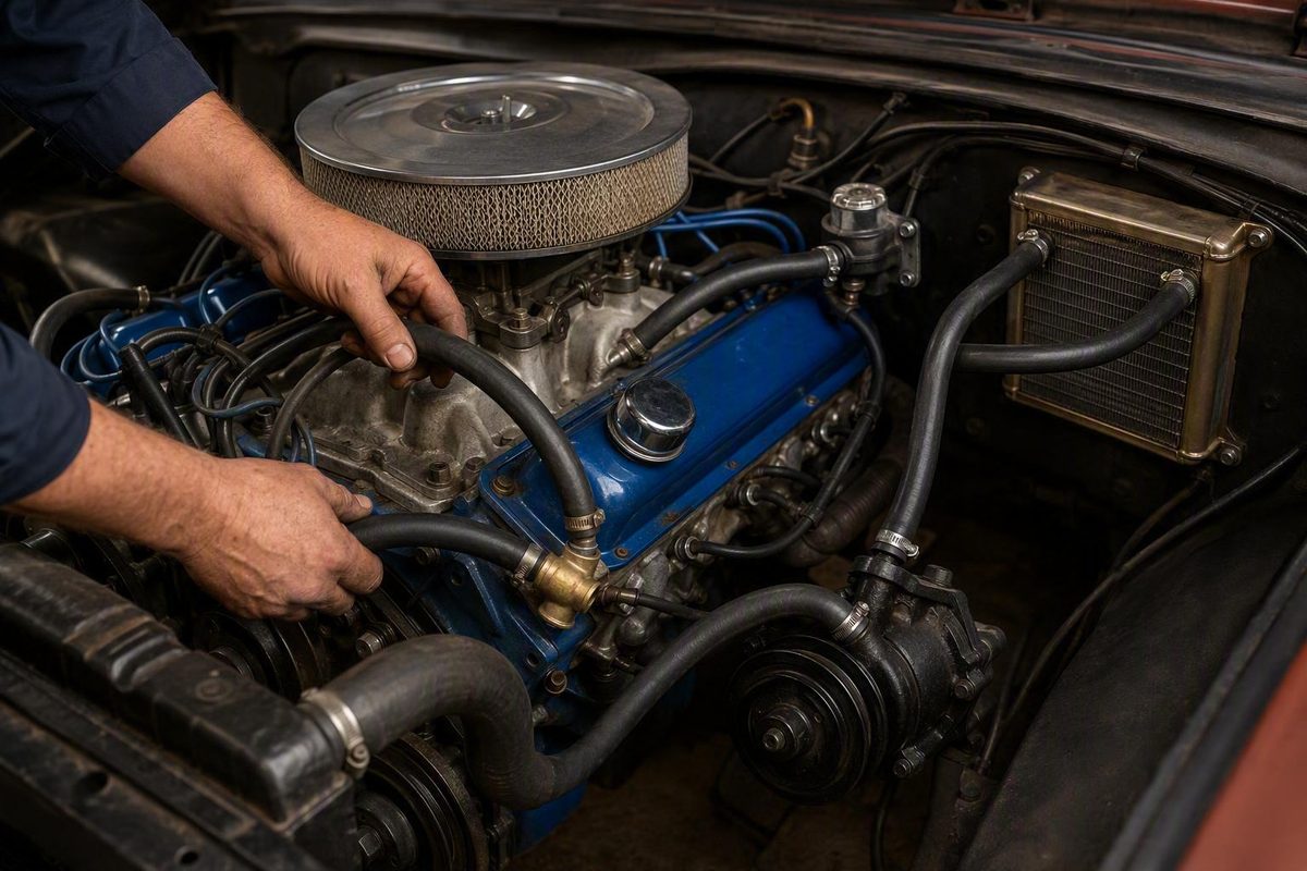
Identify the intake supply, control valve, heater core and documented pump return; preserve the thermostat bypass and plan a kink-free, heat-safe path.
For a 351 Windsor with a retained cabin heater, the commonly reported circuit is intake-manifold hot-coolant port → heater-control valve → heater core → water-pump return fitting. The short thermostat-housing-to-water-pump bypass is a separate engine circuit and must not be mistaken for a heater hose. This is a functional routing guide—not a universal nipple-location diagram—and the exact connections must be verified for the installed intake, timing cover, water pump, accessory drive, and chassis. The basic pattern and bypass distinction are reported in a 351W Explorer-serpentine installation discussion, but that source is owner guidance rather than Ford service documentation (ClassicBroncos discussion).
The typical 351W heater-hose routing
Basic retained-heater circuit:
Intake coolant port near the thermostat passage
        ↓
Heater-control valve
        ↓
Heater core
        ↓
Documented water-pump return fitting
That pattern recurs across the supplied carbureted, EFI, V-belt, and Explorer-serpentine examples. It does not establish that a particular upper, lower, left, right, driver-side, or passenger-side nipple has the same function on every 351W installation.
The heater-control valve is generally reported in the hot supply hose between the intake and heater core. If the installed valve has a flow arrow, mounting instructions, or application-specific requirements, those instructions take precedence over a generic routing description.
Treat the job as two separate decisions:
- Establish the circuit. Verify the intake-side hot-coolant supply, the heater valve, the core connections, the pump return, and the separate thermostat bypass.
- Place the hoses. Find a physical route that avoids exhaust heat, moving parts, sharp edges, electrical terminals, and other obstructions.
A shorter path is not automatically the correct path. Do not move a hose to an unidentified port merely because that port offers easier access.
Identify the ports by function, not by position
Start by identifying the dedicated engine bypass. On the configurations described in the supplied evidence, this is the short connection between the thermostat-housing area and the water pump. Once that circuit is positively identified, determine whether the remaining documented pump fitting is intended to accept the heater return.
| Connection | Function | Identification checkpoint | Common mistake |
|---|---|---|---|
| Intake heater supply | Sends hot coolant toward the valve and core | Port communicating with the intake coolant passage near the thermostat | Selecting a convenient threaded opening without verifying its passage |
| Water-pump heater return | Returns coolant from the core | Fitting identified for heater return in the pump, timing-cover, or vehicle documentation | Assuming nipple position determines function |
| Thermostat bypass | Provides the separate short bypass circuit | Direct connection between the thermostat area and water pump | Using it as one of the cabin-heater hoses |
| Heater-core fittings | Carry coolant through the core | Determine from vehicle plumbing, valve arrangement, and heater documentation | Copying firewall orientation from another chassis |
Aftermarket intake manifolds may place usable coolant ports differently. A heater-supply fitting must open into the appropriate coolant passage near the thermostat area; the presence of threads alone does not prove that a hole is a suitable heater outlet.
Use this stop/go sequence when the pump or intake is unfamiliar:
- Record the pump, timing-cover, and intake part numbers or casting identifiers.
- Find the manufacturer’s diagram or application documentation for those exact components.
- Identify the thermostat-bypass connection.
- Verify which remaining pump fitting is assigned to the heater return.
- Confirm that the proposed intake port communicates with the required coolant passage.
- Stop if the ports still cannot be identified by documentation. Visual position alone cannot resolve an unknown configuration.
Avoid rules such as “always use the upper pump nipple” or “the passenger-side heater tube is always the inlet.” Those descriptions can change with the pump, timing cover, accessory drive, firewall layout, A/C equipment, and the direction from which the engine is viewed.
Before ordering parts, record:
- Vehicle and model year
- Factory, modified, or deleted A/C equipment
- Intake-manifold make and model
- Water-pump and timing-cover configuration
- V-belt, Explorer serpentine, or other accessory drive
- Location and diameter of both firewall fittings
- Heater-valve type and marked flow direction
- The obstruction the reroute must avoid
These details are more useful than the engine family alone when searching for an applicable diagram.
Plan the new route before cutting hose
This section is a routing checklist, not a substitute for the vehicle’s cooling-system, lifting, or service instructions. Before opening the circuit, use the applicable service procedure to determine when the engine is safe to work on, how pressure is relieved, and how much coolant must be drained. Do not rely on this overview as a complete cooling-system safety procedure.
After confirming both endpoints, lay out the proposed path without cutting the final hose.
Review the entire path for:
- Headers and exhaust manifolds
- Belts, pulleys, fans, and tensioners
- Carburetor linkage, choke hardware, or EFI components
- Steering shaft and linkage
- Hood hinges and underhood bracing
- Sharp sheet-metal edges and exposed threads
- Alternator and starter terminals
- Brackets that could pinch or rub the hose
Account for movement rather than checking clearance only with the vehicle parked.
Where steering movement could affect the route, inspect clearance through the steering system’s full travel. If that inspection requires raising the vehicle, follow the approved lifting and support procedure for that vehicle rather than improvising support.
There is no supported universal clearance measurement for every header, chassis, and accessory combination. The practical goal is a route that cannot be heated, abraded, pinched, stretched, or contacted by a moving component. Add suitable supports where needed so the hose cannot fall toward a belt, pulley, exhaust part, or linkage.
Choose hose and fittings that will not kink
| Option | Best use | Main advantage | Verify before use |
|---|---|---|---|
| Bulk heater hose | Long, gradual runs | Easy to size and position | Bend radius and support locations |
| Molded elbow hose | Tight firewall or pump turns | Maintains a compact bend | Nipple sizes and elbow-leg lengths |
| Angled intake fitting | Local intake, carburetor, or EFI interference | Redirects the hose at the port | Thread type, sealing method, and tool access |
| Factory-style metal tube | Installations designed for formed tubing | Controls routing and mounting | Chassis, intake, valve, and bracket compatibility |
Model-specific Cougar owner reports illustrate why application details matter: A/C and non-A/C arrangements differed, and tight turns were handled with molded hose bends rather than sharply bending generic straight hose. That example supports using the right hose shape, not copying a Cougar layout onto another chassis.
Measure every nipple before ordering hose. A nominal 5/8-inch hose is reported in multiple 351W-related installations, but the supplied evidence does not establish that size as universal. If the connections differ, use a purpose-made reducer, transition fitting, or mixed-size molded elbow rather than forcing the wrong hose onto a nipple.
One early-Bronco contributor identified the Gates 28471 as a 5/8-by-40-inch hose that could provide useful turns near that vehicle’s heater core. Treat that as an application example only—not a guaranteed fit for another 351W, firewall, intake, or accessory layout (ClassicBroncos discussion).
Connect the circuit and verify the installation
Proceed only after the component documentation confirms the endpoints. Install the heater-control valve in the supply line before the core, following any flow arrow or orientation instruction supplied with the valve.
Use the documentation for the vehicle and installed cooling components to determine:
- Correct clamp type and placement
- Coolant specification and mixture
- Refill procedure
- Air-bleeding sequence
- Valve and heater-core orientation
- Any required inspection after refilling
A generic coolant, torque, or bleeding specification is inappropriate when the intake, pump, radiator, expansion system, and chassis may come from different applications.
During the documented refill and warm-up procedure, inspect the intake fitting, valve, firewall tubes, pump connection, clamps, and any reducers. Confirm that each hose remains round and does not kink, flatten, or collapse.
Operate the heater controls and check whether the cabin produces heat. Also inspect the passenger compartment for coolant odor, staining, damp carpet, or liquid around the heater case. Follow the applicable cooling procedure before reopening the system or correcting the coolant level.
After the initial heat cycle, inspect the route again. Verify that the hose still clears the exhaust, steering, and accessory drive and that every connection remains dry.
Treat a previously bypassed heater core as a warning
Before restoring flow, look for:
- Coolant staining around the firewall tubes
- Damp carpet or dried residue in the passenger footwell
- Deposits around the heater case or drain
- Split, hardened, or swollen hoses
- Corroded heater-core fittings
- A seized, cracked, or visibly leaking control valve
If the heater core is tested separately, obtain a pressure limit and method appropriate to that exact core. Do not apply an assumed universal test pressure to an unidentified vintage or replacement unit.
The risk is illustrated by installation-specific reports. In one 351W-powered early Bronco, restoring the heater produced cabin heat but also exposed a coolant leak into the interior (ClassicBroncos owner report). In another Bronco, reconnecting the circuit revealed a leaking core; replacement initially restored heat, although the owner later reported another core leak (Full Size Bronco discussion). These examples justify inspection, but they do not establish that every bypassed core is defective.
Heater deletion is a different job from rerouting a working heater. The supplied owner discussions disagree about looping the heater connections versus capping the intake and pump connections separately. Do not prescribe either arrangement without documentation for the exact intake, pump, timing cover, and cooling-system design. Whatever deletion method applies, do not confuse the heater circuit with the separate thermostat bypass.
Does an Explorer reverse-rotation serpentine water pump reverse heater-hose flow?
Not according to the supplied Explorer-conversion discussion. Participants report that the reverse-rotation pump uses an impeller intended for that shaft direction, allowing the cooling system to retain its normal functional circulation rather than reversing heater flow solely because the pulley turns the other way (ClassicBroncos discussion).
That is forum-sourced installation guidance, not a universal Ford specification for every pump sold as “reverse rotation.” Verify that the exact water pump matches the installed serpentine drive, and identify the heater supply and return from component documentation rather than inferring them from pulley rotation.
Can I copy the heater-core inlet orientation from another 351W vehicle?
No—not as a universal rule. Owner discussions report that some conventional cores produce heat with flow in either direction, while application-specific arrangements still assign particular firewall tubes as supply and return. For example, one owner described a specific left/right arrangement for a 1970 Mach 1 with a 351W, A/C, and a passenger-side pump inlet; those qualifications prevent it from becoming a general Windsor rule (Vintage Mustang Forums).
Use the exact vehicle or heater-system documentation when available. If it cannot be found, identify the intake supply and pump return first, inspect the control valve’s markings, and verify the core plumbing before connecting it.
The final checkpoint is functional: preserve the thermostat bypass, verify the intake-side hot-coolant supply and documented water-pump return, and only then choose the safest physical hose path. If those functions cannot be confirmed from the installed parts, stop and obtain documentation for the exact intake, pump, timing cover, heater assembly, and chassis rather than copying another vehicle’s nipple positions.