
Choose the Right Compressor—and Keep the Spring Under Control
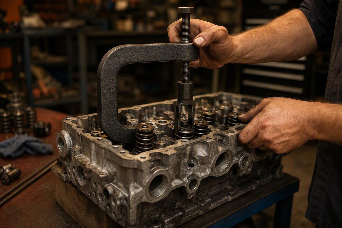
A C-clamp valve spring compressor is primarily a bench tool for a removed cylinder head. Its frame reaches around the head so one contact can support the valve face while an adapter presses the spring retainer from the opposite side. That geometry makes the tool controlled and useful when it fits, but unsuitable for many heads-on jobs and some overhead-cam castings.
Before buying, confirm the compressor’s opening, throat reach, retainer-adapter fit, keeper access, casting clearance, spring arrangement, and rated load.
During use, support the head securely, align both contacts with the valve stem, compress only far enough to free the keepers, and verify that both keeper halves are seated before releasing the spring.
First Decide: Is a C-Clamp Compressor the Right Tool for This Job?
Start with one question: Is the cylinder head removed?
A conventional C-clamp compressor presses between two sides of the valve assembly:
- One contact centers on the valve face in the combustion chamber.
- The other presses against the spring retainer.
- The frame spans the cylinder head between those points.
You therefore need access to both sides of the head. C-shaped off-engine compressors are commonly treated as bench tools for this reason, although off-engine compressors vary in frame shape and operating mechanism (OnAllCylinders’ compressor-selection guide).
If the head remains installed, do not treat the work as a variation of the heads-off procedure. A conventional compressor’s lower contact cannot reach the valve face, and releasing the keepers introduces a separate risk: the valve can drop into the cylinder. Heads-on service therefore requires:
- An on-engine compressor matched to the valvetrain.
- Adequate clearance around the rocker area, firewall, brake booster, and adjacent components.
- An engine-specific method of retaining the valve.
- The service procedure for that engine.
Depending on the valvetrain, the suitable compressor may be a compact screw-operated tool, a rocker-stud lever, a pedestal-mounted fixture, or another application-specific design. Do not assume compressed air, rope, or piston position is acceptable for every engine; use only the retention method specified for the application.
Next, confirm that the engine uses coil valve springs. A clamp compressor shortens a coil spring enough to unload the keepers. It does not apply to a non-coil arrangement. Certain vintage Honda CB450, CL450, and CB500T DOHC engines, for example, use torsion-bar valve gear rather than the coil-spring arrangement addressed here (Common Motor’s valve-spring compressor guide).
A workshop may legitimately need several compressor styles because the correct choice changes with:
- Spring and retainer geometry
- Spring force
- Single- or dual-spring construction
- Rocker-stud or pedestal configuration
- Overhead-cam casting shape
- Access near the firewall or brake booster
- Whether the head is installed or on the bench
- Frequency of use
Use this decision path:
- Removed head, coil springs, and access to the valve face and retainer: Measure the assembly and evaluate a C-clamp compressor.
- Installed head: Select an application-specific on-engine compressor and follow the prescribed valve-retention procedure.
- Non-coil valvetrain: Stop and follow the engine service manual.
- Uncertain geometry or spring force: Do not buy from a “universal fit” claim; establish dimensions and capacity first.
How the Compressor Holds the Valve Spring
A C-clamp compressor creates a load path along the valve axis. The frame reaches around the cylinder head, its lower contact sits centrally on the valve face, and a cup-shaped or open-sided pusher presses on the spring retainer.
As the tool closes, the retainer moves toward the cylinder head while the valve remains supported from below. This unloads the two tapered keepers—also called locks or collets—from the valve-stem groove. Once unloaded, both keeper halves can be removed. During installation, the same action exposes the groove so the keepers can be positioned before the retainer is lowered onto them.
A typical manual kit may include:
- A C-shaped frame
- A threaded operating screw
- A valve-side contact pad or screw tip
- Extension screws or rods
- A pusher
- Several cup-shaped retainer adapters or collets
- A molded storage case
For example, Orion Motor Tech describes one 10-piece manual kit as containing a wide C-clamp, extension screws, pushers, five collet sizes, and a case. That accessory count describes what is supplied; it does not establish which heads the kit will fit (Orion Motor Tech’s kit listing).
The selected adapter must:
- Contact the retainer evenly
- Remain square to the valve stem
- Clear the valve stem
- Leave both keeper halves accessible
- Act on the intended assembly through the retainer
- Clear the surrounding head casting
An adapter that merely fits over the spring is not necessarily correct. If it rocks, touches one side first, traps the keepers, or catches only part of a multi-spring assembly, the setup is unsuitable.
Operating mechanisms also differ:
-
Threaded compressors advance with a screw and remain in position without continuous hand force.
-
Pneumatic C-clamp tools also exist, but their operating requirements and specifications are product-specific.
Do not assume every C-shaped tool functions identically. Frame geometry, contact design, adjustment method, permitted drive method, capacity, and instructions can differ substantially.
Measure Before You Buy: Compatibility Worksheet
“Automotive,” “motorcycle,” “small engine,” and “universal” are market categories—not fit measurements. Match the exact cylinder head and spring assembly to the published specifications for the exact compressor.
Complete this worksheet before ordering:
| Compatibility item | How to determine it | Your measurement or requirement | Candidate-tool specification |
|---|---|---|---|
| Required clamp opening | Measure the relaxed span from the valve-side contact point to the retainer-side contact point | ____ mm/in | ____ mm/in |
| Required compression travel | Determine how far the retainer must move to expose the keeper groove | ____ mm/in | ____ mm/in |
| Throat depth or reach | Measure from the head’s outer edge to the valve axis along the likely tool approach | ____ mm/in | ____ mm/in |
| Valve contact position | Confirm where the lower pad can center on the valve face without touching the chamber or casting | ____ | ____ |
| Retainer outside diameter | Measure the widest diameter the adapter must straddle or contact | ____ mm/in | ____ mm/in |
| Adapter contact diameter | Determine the diameter needed to bear evenly on the retainer | ____ mm/in | ____ mm/in |
| Keeper-access opening | Measure the access needed for a magnet, tweezers, or pliers to reach both keepers | ____ mm/in | ____ mm/in |
| Surrounding casting clearance | Check cam towers, bucket bores, bosses, studs, and casting walls | ____ mm/in | ____ mm/in |
| Spring arrangement | Record single, dual, nested, or other coil-spring arrangement | ____ | ____ |
| Maximum service force | Determine the maximum spring force at the compressed height needed to service the keepers | ____ lb/N | Rated to ____ lb/N |
| Extension requirement | Determine whether an extension is needed while retaining adequate thread engagement | ____ | ____ |
| Instructions available | Confirm setup, inspection, capacity, and operating instructions are provided | Yes/No | Yes/No |
Opening is the distance the compressor must span between its valve-side and retainer-side contacts. The tool needs enough adjustment to fit over the relaxed assembly and enough usable travel to expose the keeper groove.
Throat depth, or reach, is how far the frame must extend over the head before its contacts align with the valve stem. A compressor can open wide enough yet still fail to fit because its frame strikes the side of the head before reaching the valve axis.
As a product-specific example, ToolPRO states an opening-adjustment range of 75–165 mm and 150 mm of throat clearance for its lever-operated compressor. Those figures apply only to that tool and illustrate the specifications buyers should seek (ToolPRO instructional video).
Adapter and keeper clearance
Nominal clamp size cannot establish adapter fit. The adapter must clear the valve stem and keeper groove while pressing evenly on the retainer. Its opening must also let you retrieve and install both keepers without disturbing the loaded tool.
Measure the actual retainer—not just the spring’s outside diameter—and check:
- Where the adapter will bear
- Whether its rim clears nearby casting features
- Whether its opening exposes both keepers
- Whether the valve stem remains centered
- Whether it can travel far enough without bottoming elsewhere
Overhead-cam heads deserve particular scrutiny. Cam-bearing towers, bucket bores, deep spring pockets, and narrow casting windows can block the frame or keeper access even when the listed opening and reach appear adequate.
Single versus dual springs
Record the complete spring arrangement. On a dual-spring assembly, the compressor must transfer force through the retainer to the intended complete assembly; it must not catch only the outer spring or load the retainer unevenly. One documented forum case involved an overhead-style tool gripping only the outer member of a dual-spring assembly, illustrating why the arrangement must be inspected rather than inferred from jaw size (Team Chevelle dual-spring discussion).
Capacity matters independently of size
For heavy, dual, or high-pressure springs, require a published working-load rating suitable for the maximum force reached during the compressor’s actual service travel. Obtain the relevant force at the required compressed height from verified engine or spring specifications, then ensure the tool’s rating is directly comparable.
A description such as forged, alloy, heat-treated, or black oxide does not provide a working-load rating. Neither do frame thickness, tool weight, customer reviews, or adapter count.
The no-buy rule is simple: if the seller or manufacturer cannot provide the critical dimensions and an appropriate, comparable capacity where load is material, compatibility remains unconfirmed. Do not assume the tool can be forced to fit.
Choose a Tool by Application, Not by a Universal-Fit Label
There is no defensible “best overall” compressor without defining the head, spring force, working environment, and frequency of use. Compare designs by application.
| Use case | What to prioritize | Likely direction |
|---|---|---|
| Occasional small-engine or motorcycle work | Compact reach, small adapters, sufficient opening, verified head fit | Manual C-clamp kit sized for that head |
| General automotive head rebuilding | Published opening and reach, useful adapter range, stable operation, replacement parts | Substantial bench compressor |
| Heavy or dual-spring work | Comparable load rating, rigid alignment, adapter acting through the complete retainer | Rated heavy-duty compressor |
| Repeated professional use | Documented specifications, service parts, consistent alignment, suitable operating mechanism | Professional threaded, fixture-type, or pneumatic tool |
| Heads-on service | Valvetrain-specific mounting and engine-bay clearance | Compact screw, stud, pedestal, or lever design—not the conventional heads-off procedure |
Entry-level manual kits
Budget kits often combine a wide clamp with extension screws, pushers, multiple adapters, and a case.
Do not treat piece count as a proxy for usable range. Five adapters that do not fit the retainer, clear the casting, or expose the keepers add no compatibility. Likewise, claims that a tool fits almost any automotive or small-engine head are promotional unless supported by dimensions, capacity, and a relevant application list.
Marketplace feedback can provide anecdotal usability context but cannot establish structural capacity. On one ATP listing, verified buyers reported that the tool worked, while another described it as clumsy and below premium-tool quality. Those comments do not prove safe load, longevity, or suitability for a particular head (ATP marketplace listing).
General automotive and heavy-duty threaded tools
For regular automotive head work, a threaded mechanism can be useful because it holds its position while the operator handles the keepers. Evaluate frame reach, screw engagement, adapter stability, replacement-part support, and documented capacity—not just the mechanism.
A Summit Racing Pro Billet compressor featured in a secondary tool-selection guide is reported to accept retainers from 0.850 to 1.650 inches and handle spring loads up to 1,000 pounds. These are product-specific, secondary-source figures and must not be generalized to other C-clamp compressors.
Even a rated tool is not automatically compatible. Its frame and adapter must fit the head, and the setup must preserve access to both keepers.
Professional and pneumatic tools
Regis Manufacturing lists an RL-700N air-powered C-clamp valve lifter and a replacement screw assembly for several RL-700-series tools. The supplied category page does not publish the unit’s air requirements, operating capacity, detailed dimensions, or compatibility, so those specifications require confirmation before purchase (Regis Manufacturing’s product category).
“Pneumatic” describes how the tool is actuated; it does not by itself establish strength, safety, or compatibility. Require the same documented capacity, correct contact geometry, square alignment, and controlled release expected of a manual tool.
Compare ownership, not just advertised price
Include:
- Tool and required-adapter cost
- Shipping and taxes
- Whether the necessary components are included
- Current inventory
- Return policy and restocking conditions
- Warranty
- Replacement screws, pads, adapters, and seals
- Manufacturer instructions
- Published opening, reach, travel, and capacity
- Storage and maintenance requirements
Recheck every price, shipping charge, stock state, warranty, and return condition immediately before purchase. Those terms can change, and a low advertised price may not represent the lowest delivered or long-term ownership cost.
Without controlled comparative testing, there is no basis here to rank brands for safety, strength, durability, or value.
Prepare the Cylinder Head and Work Area
A compressed valve spring is under high tension. If the tool slips or a keeper comes loose, small metal parts can be ejected. Wear suitable eye protection whenever the spring is being compressed or released, and stay out of the likely path of ejected parts (Common Motor’s safety guidance).
Follow the service manual for the exact engine. It should control component order, spring orientation and specifications, valve-stem-seal handling, lubrication, inspection, and model-specific precautions. This guide covers compressor selection and a general heads-off workflow; it does not replace engine- or tool-specific instructions.
Prepare the work as follows:
- Clean and organize the bench. Remove clutter that could hide a dropped keeper.
- Support the cylinder head. Place it on a suitable stand or solid blocks so it cannot rock, tip, or slide.
- Protect machined surfaces. Use supports that will not mark the deck or other finished surfaces.
- Preserve access. Keep the supports clear of the valve face, retainer, and compressor frame.
- Label every valve location. Use numbered bags, a compartment tray, or a marked rack so parts can return to their original locations unless the prescribed repair process says otherwise.
- Lay out handling tools. Have a magnetic pickup tool, tweezers or suitable needle-nose pliers, small keeper containers, and a small amount of grease within reach.
- Select the adapter and extensions. Confirm they match your measurements and provide the engagement required by the tool manufacturer.
- Put on eye protection before loading the spring.
Inspect the compressor as directed by its manufacturer. Before use, look for visible cracks, bending, distortion, damaged or contaminated threads, a deformed screw end, a loose contact pad, bent extensions, distorted adapters, poor-fitting joints, or inadequate thread engagement. Do not invent a wear limit or repair method; if condition is uncertain, obtain manufacturer guidance or replace the tool.
Dry-position the tool
Place the compressor over the unloaded assembly before tightening it. Confirm that:
- The head remains stable.
- The lower contact sits centrally and fully on the valve face.
- The adapter sits squarely on the retainer.
- Both contacts align with the valve-stem axis.
- The frame clears the casting throughout the anticipated travel.
- The adapter leaves access to both keepers.
- Extensions are straight and properly engaged.
- The spring arrangement and maximum service force are within the documented capability.
Stop before applying or increasing load if the support is unstable, the adapter rocks, the contacts are off-axis, threads bind or appear damaged, the frame interferes with the head, keeper access is blocked, or capacity is uncertain.
Remove a Valve Spring Step by Step
This procedure is for a removed cylinder head using a compatible compressor. It is not an on-engine procedure and does not provide a method for retaining a valve inside an assembled engine.
-
Confirm the valve identity. Verify that the valve and associated parts have a marked storage location.
-
Stabilize the head. Make sure the combustion-chamber side and spring side remain accessible. The head should not rock when pushed gently in several directions.
-
Install the correct adapter and extension. The adapter must contact the retainer evenly and leave both keepers reachable.
-
Center the lower contact. Position it on the center of the valve face, not on an edge or against the surrounding combustion chamber.
-
Center the retainer adapter. Keep it square to the retainer and align the compressor with the valve stem.
-
Take up slack slowly. Establish firm contact, then recheck the valve-side pad, adapter, frame clearance, extension alignment, and head support.
-
Compress gradually. Monitor the complete load path. The contacts must stay centered, the spring must remain straight, and the tool must not slip or visibly distort.
-
Stop when both keepers are free. Compress only enough to expose the valve-stem groove and unload both keeper halves. The demonstrated clamp-style procedure calls for slow operation and only the travel needed to access the groove.
-
Abort an unstable setup safely. If the adapter shifts, the spring tilts, a contact slips, the head moves, or the frame begins to deflect, stop and release the tension gradually. Do not straighten or recenter the setup while it remains loaded.
-
Remove both keepers. Use a magnetic pickup tool where practical. Use needle-nose pliers only when they can reach the keepers without bumping the adapter or moving the compressor.
-
Account for both halves immediately. Place them in the marked container. If one is missing, inspect the retainer recess and work area before continuing.
-
Release the compressor gradually. Watch both contacts while the retainer rises and the spring unloads. Do not release the mechanism abruptly.
-
Remove parts in order. Lift off the retainer, spring or complete spring assembly, and spring seat as directed by the engine procedure. Store them by valve location.
-
Continue according to the engine manual. Do not force a valve through its guide. Valve, guide, seal, seat, and stem work requires the applicable inspection and service procedure.
Reinstall the Spring and Verify the Keepers
Installation is not complete merely because the keepers stay in place while the compressor is tight. Both halves must engage the valve-stem groove evenly and capture the retainer as spring force is transferred back to them. Improperly seated keepers can come loose as tension is released, allowing parts to be ejected.
First, use the engine service manual to confirm:
- Correct spring and seat
- Spring orientation
- Valve-stem-seal installation
- Retainer orientation
- Required lubrication
- Component order
- Reuse or replacement rules
Return labeled valves and associated parts to their original positions unless the prescribed repair process requires otherwise.
Then reinstall the assembly:
-
Position the lower components. Install the seat, seal, and any other specified parts in the prescribed order.
-
Place the spring assembly. Confirm its orientation and ensure nested springs and any damper are arranged as specified.
-
Install the retainer. It should sit normally on the spring before compression.
-
Realign the compressor. Center the lower contact on the valve face and the adapter on the retainer. Reconfirm stable support and valve-axis alignment.
-
Compress slowly. Stop when the complete keeper groove is exposed.
-
Prepare the keeper halves. A small dab of grease can help hold them during placement. Do not use so much that it obscures the groove.
-
Install both keepers. Use tweezers, suitable pliers, or a magnetic tool without leaning on the compressor or adapter.
-
Inspect before releasing. Both keepers should occupy the same groove, sit at the same height, and surround the stem symmetrically.
-
Transfer the load cautiously. Release a small amount of compressor pressure while watching the retainer move onto the keepers. If either keeper rises, tilts, shifts, or sits lower than the other, stop and recompress.
-
Release gradually. Continue only after symmetrical engagement is clear.
-
Perform a final inspection. Check keeper symmetry, retainer position, spring alignment, seat position, and component order before proceeding to the next valve.
Visual confirmation during the initial load transfer is essential. Spring pressure alone is not proof that both keeper halves are seated correctly.
Troubleshooting Poor Fit, Slippage, and Difficult Keepers
For any movement or off-center loading, release spring tension fully and gradually before repositioning anything. Do not push a loaded frame sideways, tap an adapter into place, or try to straighten an angled spring.
| Problem | Likely issue | Response |
|---|---|---|
| Insufficient opening | Required span exceeds the tool’s range, or the wrong approved extension is installed | Unload the tool; verify the measurements and permitted extension setup. Select a larger compressor if necessary. |
| Inadequate throat reach | Frame contacts the head before reaching the valve axis | Use a compressor with greater reach or different frame geometry. |
| Frame interference | Cam tower, bucket bore, boss, or casting wall blocks positioning or travel | Change approach only if the instructions permit it; otherwise choose a different tool geometry. |
| Adapter too large | It contacts the casting, traps the keepers, or cannot center on the retainer | Use a smaller compatible adapter that still bears evenly on the retainer. |
| Adapter too small | It contacts the stem, enters the wrong area, rocks, or loads the retainer unevenly | Use the correct larger adapter; do not continue with partial contact. |
| Keepers inaccessible | Adapter opening is too narrow or poorly oriented | Unload the tool and select an adapter that exposes both keeper halves while remaining stable. |
| Keeper groove remains covered | Adjustment, adapter height, extension selection, opening, or travel is wrong | Unload and inspect the setup rather than automatically applying more force. |
| Angled loading | Contacts are off-center, the adapter rocks, or frame geometry is incompatible | Release fully, recenter, and reassess. Use another tool if square loading cannot be maintained. |
| Slipping contacts | Valve pad or adapter is not seated, or the head is moving | Release fully, stabilize the head, and correct both contacts. |
| Binding threads | Dirt, damage, misalignment, overload, or inadequate engagement may be present | Stop using the tool and follow its manufacturer’s inspection instructions. |
| Visible frame deflection | Load may exceed capacity, alignment may be poor, or the tool may be damaged | Release gradually and discontinue that setup until capacity, condition, and alignment are verified. |
| Adapter catches only part of a dual spring | Adapter or compressor geometry is wrong | Stop and use a setup that transfers force through the retainer to the intended complete assembly. |
| One keeper will not seat | Groove is not fully exposed, keeper orientation is wrong, or retainer is misaligned | Maintain control, recompress if needed, and correct placement without unnecessary travel. |
| Keepers move during release | Engagement is uneven or the retainer is misaligned | Stop, recompress, reinstall both keepers, and verify symmetry again. |
When more force is not the answer
If the keeper groove does not become accessible, verify:
- Initial screw adjustment
- Extension length and installation
- Adapter height
- Tool opening and available travel
- Whether the retainer is moving
- Whether the adapter has bottomed on another component
- Whether the frame is contacting the head
- Whether another component has reached a mechanical limit
Force cannot compensate for insufficient reach, incorrect adapter geometry, or blocked travel. If an overhead-cam casting blocks the frame or leaves no route to the keepers, change compressor geometry rather than operating the tool at an angle.
If threads bind, show damage, or engage only partially, stop. Do not use a drill, impact tool, lubricant, thread repair, or replacement fastener unless the specific manufacturer’s instructions authorize it. Permission to use a powered drive on one compressor does not apply to another.
Bending, welding, grinding, or otherwise modifying a load-bearing compressor is outside this procedure. One forum contributor described making an overhead-cam compressor from a C-clamp and a socket with a keeper-access window cut into it. The report provides no load rating, fabrication specification, or proof that the socket was structurally suitable as a compressor component, so it should not be treated as equivalent to a rated purpose-made tool (Grassroots Motorsports forum account).
Choose another compressor—or professional cylinder-head service—when you cannot verify fit, capacity, alignment, stable support, thread engagement, keeper access, or final keeper seating.
Frequently Asked Questions
Can a C-clamp valve spring compressor be used with the cylinder head still on the engine?
A conventional model generally cannot because it requires access to both the spring retainer and valve face. Heads-on service normally calls for a compact screw-operated, rocker-stud-mounted, pedestal-mounted, or lever-style compressor selected for the valvetrain and available clearance.
It also requires an engine-specific method to prevent the valve from dropping into the cylinder. Do not adapt the heads-off procedure without the applicable service instructions.
How far should I compress a valve spring?
Compress it only far enough to expose the valve-stem groove and free or install both keepers. If the groove remains inaccessible, unload the tool and check adjustment, adapter height, extensions, reach, and interference before trying again.
How do I choose the correct retainer adapter or collet?
Choose an adapter that sits squarely on the retainer, contacts it evenly, clears the valve stem, and leaves both keepers accessible. It must also clear the casting and transfer force through the retainer to the intended spring assembly.
Do not choose from approximate spring diameter alone. Measure the retainer and available access, then compare those measurements with published adapter dimensions.
Will a budget C-clamp compressor work on dual or high-pressure springs?
Possibly, but price and frame appearance cannot answer the question.
If the tool is unrated, catches only an outer spring, deflects, or cannot remain aligned, do not use it for that assembly.
What should I do if the valve keepers will not stay in place during installation?
Use a small dab of grease to help hold each keeper while placing it with tweezers, suitable pliers, or a magnetic tool. Expose the complete groove and avoid touching the loaded compressor unnecessarily.
Before release, verify that both halves sit at the same height and engage the groove evenly. Let the retainer move onto them by releasing only a small amount of pressure. If either keeper shifts or tilts, stop, recompress, and reinstall both halves.
The Measurement-First Recommendation
Use a C-clamp compressor when the cylinder head is removed, both sides of the valve are accessible, and the tool’s opening, reach, travel, adapter geometry, keeper access, and rated capacity match the assembly.
Do not choose by brand claims, adapter count, material descriptions, or price alone. If the setup cannot remain square and stable—or if both keepers cannot be visibly verified during release—remove the load and choose a more suitable tool or professional cylinder-head service.