
Does the Fault Happen While Cranking—or After the Engine Starts?
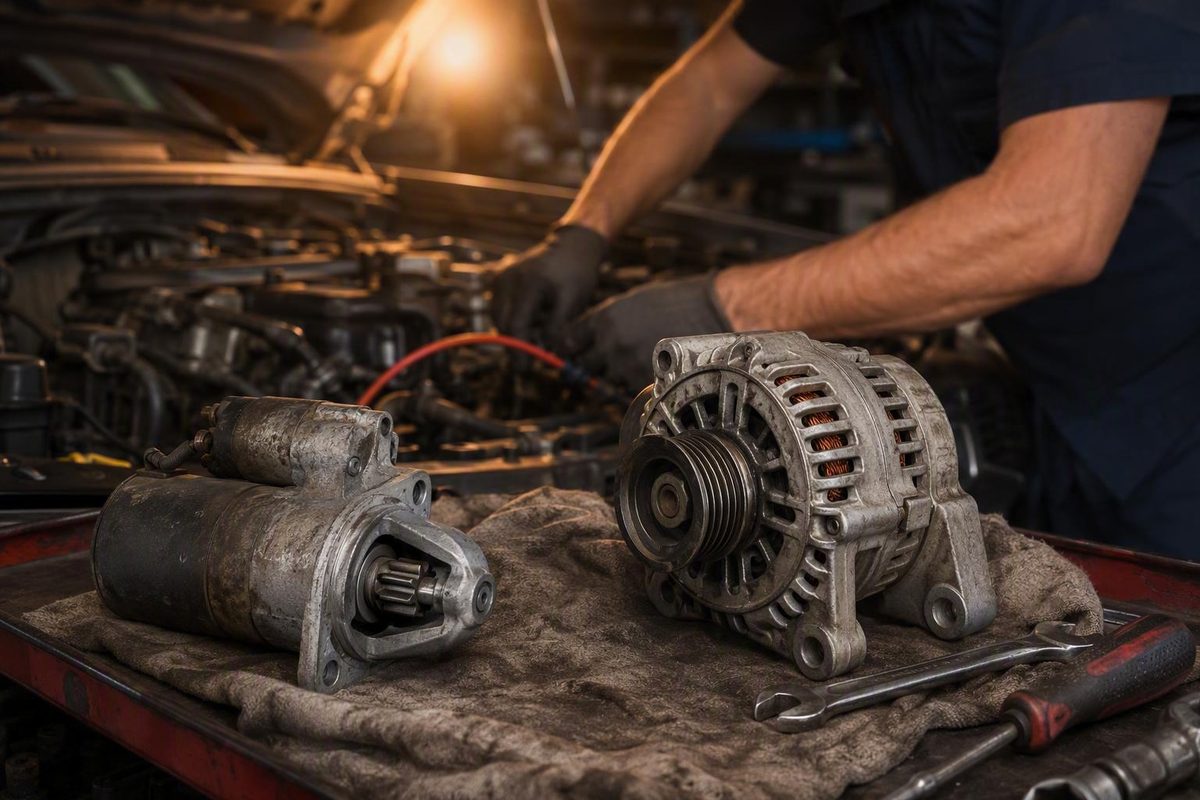
Use symptom timing to choose between battery and starting-circuit tests or charging-system checks, with loaded testing before replacing either part.
The difference between an alternator and a starter is when each component works and how it transfers energy. The starter uses stored battery energy to crank the engine during a start attempt. After the engine starts, it drives the alternator, which supplies electricity to vehicle loads and replenishes the battery.
If the engine will not crank or cranks slowly, test the battery and starting circuit first. If electrical trouble develops after startup, begin with the charging system. Symptom timing chooses the test path, but it does not prove which part has failed.
Starter vs. alternator: the difference at a glance
A conventional starter is a high-current electric motor. When you turn the key or press the start button, the starting circuit supplies battery current to the starter. Its gear engages the engine, and the motor turns the crankshaft.
Battery → starter → engine cranking
The alternator performs the opposite energy conversion. Once the engine runs, a belt or other mechanical drive turns the alternator. It converts that mechanical input into electrical output for the vehicle and battery.
Running engine → alternator → electrical loads and battery
These basic functions and the shared roles of the battery, wiring, starter, and alternator are described in the Delco Remy diagnostic manual for heavy-duty starting and charging systems. Its system principles are useful here, but its application-specific procedures and specifications should not be transferred to a passenger vehicle.
| Comparison | Starter | Alternator |
|---|---|---|
| Purpose | Turns the engine fast enough to begin running | Powers electrical loads and replenishes the battery |
| Operating phase | During a start attempt | After the engine starts |
| Energy conversion | Electrical energy into mechanical rotation | Mechanical rotation into electrical energy |
| Common complaint stage | No crank, slow crank, intermittent crank, or noise during cranking | Charging warning, weak accessories, flickering lights, or recurring discharge |
| Preliminary checks | Battery, terminals, cables, grounds, controls, and interlocks | Battery, drive belt, output wiring, grounds, fuses, and controls |
| Confirming measurements | Loaded voltage drop, available voltage, current draw, and operation against vehicle specifications | Output voltage and current, loaded circuit voltage drop, control checks, and ripple when warranted |
The components are separate, but the battery and vehicle wiring connect them. A charging fault can leave the battery discharged and produce apparent starter trouble on the next start attempt. Cable or ground resistance can also make a serviceable starter or alternator appear defective.
This guidance is limited to conventional low-voltage systems with a separate starter and engine-driven alternator. Other starting and charging architectures require procedures for the exact vehicle.
First identify what the engine is actually doing
Before connecting a meter, classify the complaint. “It won’t start” can describe several different conditions.
| What happens | What it means | Test first |
|---|---|---|
| No crank | The engine does not rotate during the start command | Battery and complete starting circuit |
| Slow crank | The engine rotates more slowly than expected | Battery, cables, grounds, starter draw, and mechanical resistance |
| Normal crank but no start | The engine rotates normally but does not begin running | Fuel, ignition, compression, security, and engine-management systems |
| Starts, then develops electrical trouble | The engine runs, but warnings, weak accessories, or battery discharge appear | Alternator drive and charging system |
A no-crank condition does not automatically mean the starter has failed. The battery may be discharged, a terminal may be loose, a ground may have excessive resistance, an interlock may be preventing operation, or the starter control circuit may not be receiving the command.
If the engine cranks at normal speed but will not run, the starter is already performing its primary function.
Trouble that appears after startup shifts the first test toward the charging system. A charging warning, changing light brightness, weakening accessories, or recurring battery discharge provides a clue, not a component diagnosis.
Check the battery and connections before either component
The starter places a much higher demand on the battery than headlights, dashboard lamps, or a radio. Accessories can still work when the battery or high-current circuit cannot support cranking. Working lights therefore do not prove the battery, cables, or grounds are healthy.
Use this inspection sequence:
- Verify that the battery terminals are correctly seated and secure.
- Look for corrosion, overheated terminals, damaged insulation, swollen cables, and loose connections.
- Inspect the battery-to-engine and battery-to-chassis grounds.
- Check the relevant starter and alternator wiring, connectors, fuses, and fusible links.
- Inspect the alternator belt and tensioning system where applicable.
- Test battery condition using the procedure specified for the vehicle and battery type.
A battery can show a plausible unloaded voltage but drop excessively under starter load or lack the required capacity.
Remember that a charging fault can become the next morning’s starting complaint. If the alternator drive or charging circuit fails to replenish the battery, the next start attempt may produce rapid clicking, slow cranking, or no crank.
A jump start is preliminary evidence only. If the engine still will not crank, poor jumper contact, inadequate cables, defective terminals or grounds, control faults, interlocks, or mechanical resistance may still be responsible. If it cranks with external support, that only establishes that the added support changed the symptom. Battery and charging tests are still required.
If it will not crank or cranks slowly, test the starting circuit
One solid click, rapid clicking, intermittent operation, slow cranking, whirring, or grinding can narrow attention to the starting system, but none proves an internally failed starter. Grinding can involve starter engagement, flywheel teeth, mounting, or alignment.
The test path may include:
- Battery
- Positive battery cable and terminals
- Starter relay and control circuit
- Starter solenoid
- Starter motor
- Engine and chassis grounds
- Ignition switch or start-button input
- Park/neutral or clutch interlock
- Security authorization and related modules
- Connectors, fuses, and fusible links
Begin with battery condition. Then determine whether the starter receives the required command and whether excessive voltage is being lost in the positive or ground path.
Use voltage-drop testing under load
A continuity check or visual inspection can miss resistance that becomes significant only when high current flows. Voltage-drop testing measures the electrical potential lost across a working cable, connection, switch, or ground. If a restriction is found, repair it and retest before considering component replacement, as explained in Fluke’s automotive voltage-drop guidance.
A basic loaded test normally follows this sequence:
- Use the vehicle-specified method to prevent the engine from starting while preserving the cranking function needed for the test.
- For the positive side, place the meter across the tested supply path—typically from battery positive to the starter feed terminal, subject to the service procedure.
- Make a brief crank attempt and record the voltage drop.
- For the ground side, test from the starter housing or engine block to battery negative, again using the specified test points.
- Test the solenoid or control circuit separately if required.
- Repair any excessive loss and repeat the same loaded test.
Do not apply one universal cranking-voltage, current-draw, or voltage-drop limit. Starter design, cable length, battery arrangement, temperature, system voltage, and probe locations vary. Use the exact vehicle’s specifications and test conditions.
The starter becomes a replacement candidate only after the battery passes its applicable checks, circuit resistance and control faults have been corrected or excluded, and the starter still fails the specified operating, voltage, or current-draw test.
If it runs but loses electrical power, test the charging system
Charging-system clues include a battery or charging warning, dimming or flickering lights, weakening accessories, abnormal electrical behavior, and repeated battery discharge. Treat them as reasons to test, not proof that the alternator has failed.
Start with a visual inspection:
- Check the alternator belt, tensioner, pulley, and alignment.
- Inspect the alternator output connection and relevant fuse or fusible link.
- Inspect the battery terminals and engine, chassis, and alternator ground paths.
- Look for loose, contaminated, damaged, or overheated wiring.
- Check the charging-system connectors and controls used by the application.
Diagnosis may require output-voltage, current-output, control-circuit, and loaded voltage-drop tests. Compare the results with service information for the exact vehicle. A generic engine-running voltage range is not a universal pass/fail standard because system design, battery condition, temperature, load, and charging strategy can affect the reading.
Resistance between the alternator output terminal and battery positive can prevent full charging even when the alternator can generate power. A poor ground path can do the same. Test these paths while the charging circuit is carrying an appropriate load.
AC-ripple testing is a secondary screen. Ripple is the residual AC voltage in the alternator’s DC output. Excessive ripple may indicate rectifier-diode or stator trouble, but poor grounds and test conditions can affect the result. Fluke’s alternator-ripple procedure calls for loading the system and checking ground integrity. Use the vehicle manufacturer’s limit instead of treating a generic ripple value as decisive.
A vehicle that starts and then stalls does not, by itself, prove alternator failure. Fuel delivery, ignition, security authorization, engine-speed input, and engine-management faults can also stop a running engine. Confirm charging output and circuit integrity.
When the test results justify replacement
The decision rule is straightforward: repair the supporting system first, then repeat the original loaded test.
Replace the starter only when:
- The battery passes its applicable condition and capacity checks.
- The positive and ground paths pass loaded voltage-drop tests.
- The starter command, solenoid circuit, and interlocks operate correctly.
- Mechanical resistance or engagement trouble has been excluded where applicable.
- The starter still fails the manufacturer’s operating, voltage, or current-draw specification.
Replace the alternator only when:
- Battery condition is known.
- The belt, tensioner, and pulley drive the alternator correctly.
- Output wiring, fuses, connections, and grounds pass inspection and loaded tests.
- Relevant charging controls operate as specified.
- Charging output, current, ripple, or another manufacturer-specified test remains outside specification.
Repeated battery discharge is not an automatic alternator diagnosis. Battery condition, charging performance, and key-off draw are separate diagnostic questions.
Take this checklist to the vehicle:
- [ ] Classify the complaint: no crank, slow crank, normal crank but no start, or post-start electrical trouble.
- [ ] Inspect terminals, cables, grounds, wiring, fuses, and the alternator belt.
- [ ] Test battery condition using the applicable procedure.
- [ ] Test the affected circuit under load.
- [ ] Repair excessive resistance or control faults.
- [ ] Repeat the original test under the same conditions.
- [ ] Replace only the component that still fails its applicable specification.
Safety limits for starting and charging tests
Starting and charging circuits can carry high current. Before testing, inspect the meter and leads, select the correct function and input terminals, and verify meter operation on a known source. Never measure voltage while a lead remains connected to a current input. Use an appropriately rated clamp-on probe for starter-current measurements rather than routing starter current through an unsuitable meter input. Consult the vehicle service manual for the applicable test and engine-disabling method, as directed by the Fluke automotive meter manual.
During running-engine tests, secure the test leads and keep your hands, clothing, tools, and leads clear of belts and pulleys. Wear suitable eye protection, and probe at a safer accessible point when the exposed alternator output terminal cannot be reached safely. These precautions are included in the cited alternator-ripple procedure.
Stop making start attempts if smoke, overheated wiring, or a burning odor appears. Such symptoms can accompany an overheated starter or electrical fault and require inspection before further cranking; starter guidance from Riverside Ford likewise treats smoke or a burning smell during repeated attempts as a warning sign rather than a reason to continue testing.
Before alternator removal, disconnect the battery as the vehicle manufacturer directs. The output terminal may remain live with the engine off. The manufacturer’s 24SI and 28SI alternator installation instructions warn that a tool contacting the output terminal and ground can heat rapidly and cause injury or damage.
These procedures do not establish the correct tests for hybrids, 24-volt vehicles, stop-start systems, smart-charging designs, belt starter-generators, or integrated starter-generators. Identify the exact system and use its model-specific service information.
The practical distinction is simple: the starter turns the engine during cranking; the alternator supports the electrical system after startup. Classify when the fault occurs, test the relevant system under load, and replace a component only when the applicable results confirm it.