
A Stator Is Usually One Part of Your Motorcycle’s Alternator
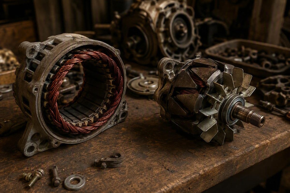
The stator’s stationary windings work with a moving rotor to form the alternator’s generating core; terminology varies by system design.
On a motorcycle, the stator is normally the stationary winding assembly inside the alternator. The alternator is the AC-generating device or assembly containing the stator and rotor. In other words, a stator is usually a component—not a separate alternative to an alternator.
That distinction does not diagnose a charging problem. Test the system before replacing a part.
The short answer: stator is the part, alternator is the generator
A motorcycle stator is a stationary set of wire windings. The rotor moves relative to those windings, creating a changing magnetic field that induces alternating current. Together, the rotor and stator form the generating core of the alternator.
The apparent “stator vs alternator” choice usually comes from informal terminology. Riders and parts listings often emphasize the stator because it is the component being tested or replaced. Meanwhile, alternator may describe either the rotor-stator generator or a broader assembly that includes the regulator/rectifier. The exact boundary varies by source and motorcycle design.
The alternator is not the complete charging system. The broader system includes:
- The rotor and stator that generate AC
- The regulator/rectifier
- The battery
- Charging-system wiring and connectors
- Fuses, grounds, and related circuit protection
On a common motorcycle layout, the rotor and stator are integrated with the engine while the regulator/rectifier is mounted elsewhere. A common automotive-style alternator packages the generating and rectification hardware in one external housing. UTI’s motorcycle charging-system comparison explains this packaging distinction.
This terminology applies to the motorcycle charging systems covered here. Do not assume that outboards, stationary generators, magnetos, or electric motors use stator and alternator in exactly the same way.
How motorcycle charging power moves through the system
The energy flow through a common motorcycle charging system is:
Engine rotation → moving rotor or magnetic field → AC induced in stationary stator windings → regulator/rectifier → regulated DC for the battery and electrical loads
The engine drives the rotor. Depending on the design, the rotor may turn inside or around the stator, but the defining relationship remains the same: the rotor moves while the stator remains stationary. The rotor’s changing magnetic field induces voltage in the stator windings.
That raw output is alternating current. The regulator/rectifier then performs two related functions:
- The rectifier converts the generated AC into DC.
- The regulator controls the output supplied to the battery and electrical system.
An alternator therefore generates AC internally even though regulated DC ultimately reaches the battery. Describing the motorcycle’s charging supply as DC does not mean the stator generates DC directly.
The battery provides the energy needed to start the motorcycle, supplies current when alternator output is lower than electrical demand, and acts as a buffer for the electrical system. Once the engine is running, the charging system supports the motorcycle’s electrical loads while restoring energy used during starting. Motorcycle Cruiser’s charging-system overview describes these roles.
Alternator output generally rises with engine speed. However, there is no universal idle voltage, test RPM, stator resistance, or AC-output threshold for every motorcycle. Those values depend on the exact charging-system design.
Motorcycle stator system vs car-style alternator
The main practical difference is packaging, not the underlying electrical principle. Both layouts generate AC internally before rectification provides usable DC to the battery.
| Comparison | Common motorcycle layout | Common car-style layout |
|---|---|---|
| Meaning | “Stator” names a component; “alternator” names the generator or assembly | “Alternator” usually identifies the complete external unit |
| Typical location | Rotor and stator integrated inside or alongside the engine | Externally mounted and driven by the engine |
| Generator components | Moving rotor and stationary stator | Rotor and stator contained in one housing |
| Raw electrical output | AC | AC |
| Rectification arrangement | Regulator/rectifier commonly mounted separately | Rectification hardware commonly contained in the alternator housing |
| Replacement scope | Components may be identified separately, depending on design | Presented as a self-contained unit; service scope depends on the vehicle and unit |
Stator wiring then connects the generator to a regulator/rectifier mounted elsewhere on the motorcycle.
A car-style alternator is more visibly distinct. It is mounted outside the engine, mechanically driven—commonly by a belt—and houses the rotor, stator, and rectification hardware.
Neither layout should be defined solely by whether it uses permanent magnets or a wound-field rotor. Designs vary. For diagnosis and parts identification, the motorcycle’s actual architecture matters more than a broad motorcycle-versus-car generalization.
Exceptions and terminology that can change by motorcycle
The engine-integrated rotor-stator arrangement is common, but it is not universal. Some motorcycles, particularly certain larger touring designs, use an externally mounted, self-contained alternator resembling an automotive unit. Motorcycle Cruiser notes both multi-piece motorcycle charging arrangements and external alternators used on some machines.
Older or specialized motorcycles may use equipment described as a generator or dynamo. Some pure race dirt bikes may also use stator output primarily for CDI ignition rather than charging a conventional battery, so their circuits and diagnostic procedures can differ from those of a battery-equipped street motorcycle. Viking Bags describes this limited dirt-bike configuration.
The cited motorcycle sources also use slightly different boundaries for the word alternator:
- One usage treats the rotor and stator as the alternator.
- Another includes the regulator/rectifier in a multi-piece alternator assembly.
- Parts catalogs may identify the stator without prominently using “alternator.”
- Service information may use terms such as generator or charging coil.
Use the exact motorcycle’s service manual and wiring diagram to determine what each component is called, which terminals serve each circuit, where rectification occurs, and which components are separately serviceable.
Charging symptoms do not prove the stator failed
Possible charging-system symptoms include:
- A battery that discharges while riding
- Headlights or other lights that dim
- Low or absent charging output
- An engine that eventually shuts down after the battery is depleted
They do not isolate the stator as the failed component.
Other possible fault areas include:
- A weak or damaged battery
- Loose or corroded battery terminals
- Poor grounds
- Damaged charging-system wiring
- Loose, backed-out, or overheated connectors
- An open fuse
- A rotor problem
- A failed regulator/rectifier
Replacing the battery without finding the charging fault will not correct the underlying problem. Replacing the stator based only on the same symptom is equally speculative.
Diagnosis should follow the complete power path: battery, terminals, grounds, fuses, connectors, charging voltage, stator windings, AC output, regulator/rectifier, and rotor or generator circuit.
A test-before-replacement charging-system workflow
This is a starting framework, not a model-independent repair procedure. Use the service information for the exact year, make, model, and engine for meter settings, connector handling, terminal pairs, test RPM, and pass/fail limits.
1. Check the battery and accessible circuit first
Verify battery condition using the motorcycle or battery manufacturer’s procedure. Inspect the battery terminals, grounds, accessible charging connectors, fuses, and wiring.
Look for looseness, corrosion, backed-out terminals, damaged insulation, discoloration, or heat-damaged connector bodies. Correct an obvious battery or connection fault before interpreting downstream measurements because excessive resistance or an open connection can distort the results.
2. Compare engine-off and running voltage
Measure battery voltage with the engine off. Then measure charging voltage with the engine running at the RPM specified for that motorcycle.
This comparison establishes whether regulated charging output is reaching the battery. A low result does not identify the failed component by itself.
Do not substitute a generic internet voltage range for the manufacturer’s test conditions and acceptable limits.
3. Test the stator only as directed
If the service procedure calls for stator testing, disconnect the specified connector and perform only the listed checks. Depending on the system, these may include:
- Continuity or resistance through specified winding pairs
- A check for unwanted continuity between a winding and ground
- AC output between designated terminals with the engine running
Use the specified meter setting, terminals, connector state, RPM, and pass/fail values. Motorcycle stator diagnosis may include both engine-off winding checks and engine-running output measurements, as outlined in UTI’s stator-testing overview.
4. Follow the result through the circuit
If the stator meets every applicable specification but regulated battery voltage remains incorrect, continue through the regulator/rectifier, wiring, connectors, and grounds. A passing stator test is a reason to move to the next part of the circuit—not to replace the stator anyway.
| Test result | Diagnostic direction |
|---|---|
| Battery or connection check fails | Correct that fault first, then retest the charging system |
| Stator winding or AC-output check fails specification | Investigate the stator and associated rotor/generator circuit |
| Stator passes but battery charging output fails | Investigate rectification, regulation, wiring, connectors, and grounds |
The usable distinction is straightforward: the stator is normally the stationary winding component within a motorcycle’s alternator, while the regulator/rectifier converts the generated AC into controlled DC. The diagnostic decision requires more care because battery, connection, wiring, rotor, stator, and regulator/rectifier faults can overlap. Identify the system design and compare each measurement with the applicable service specification before buying a part.