
Prove the Fuel Sender Is Faulty Before You Open the Tank
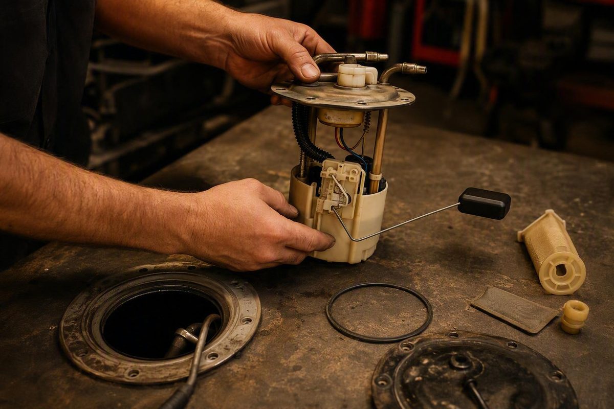
Cleaning cannot restore missing resistor material, while sender replacement is unnecessary if the only confirmed defect is an external ground.
A fuel gauge stuck on full, empty, or somewhere in between does not prove that the fuel sending unit has failed. The same symptom can come from the float mechanism, resistance element, connector, wiring, ground, voltage regulation, gauge, or instrument cluster.
That distinction matters because the sender is inside the fuel tank or attached to an in-tank pump module. Access can involve fuel vapor, residual pressure, spills, electrical hazards, and tank handling. Fuel sending unit repair should therefore begin with three questions:
- Does the rest of the gauge circuit work correctly?
- Does the sender match the exact resistance specifications for this vehicle?
- If the sender is faulty, what physical defect caused the failure?
A practical decision path is:
- Check the external circuit first.
- Test the sender against vehicle-specific specifications.
- Inspect the float, arm, pivot, wiper, and resistance element.
- Choose the least invasive remedy that addresses the confirmed defect.
- Verify the signal, gauge response, sealing, and absence of leaks before trusting the repair.
Possible remedies include cautious cleaning, correction of an external ground or serviceable contact, professional rebuilding, sender-only replacement, or complete fuel-pump-module replacement.
How the Fuel Sender and Gauge Circuit Work
A conventional fuel sending unit uses a float connected to a pivoting arm. As the fuel level changes, the arm moves a wiper across a variable-resistance element. The resulting electrical signal is interpreted by the gauge or instrument cluster. The sender is commonly attached to the in-tank fuel-pump assembly, although some applications allow it to be serviced separately (AutoZone’s fuel-gauge overview).
The sender may be:
- A separate removable component
- Attached to an in-tank fuel pump
- Available separately even though it mounts on the pump assembly
- Serviced only as part of a complete pump-and-sender module
The float and resistor are only part of the circuit. Diagnosis may also need to account for:
- Float buoyancy and movement
- Float-arm shape and travel
- Arm pivot and bushings
- Wiper pressure and alignment
- Resistance wire or printed resistor track
- Sender terminals and internal connections
- Tank connector
- Harness continuity
- Sender or flange ground
- Instrument voltage regulation
- Gauge and instrument-cluster circuitry
A poor connection anywhere in that path can change the signal reaching the gauge. A failed ground near the tank can be especially deceptive: the sender may appear mechanically intact while the completed circuit produces an incorrect reading.
Resistance direction is not universal
Do not assume that low resistance means empty or that high resistance means full. Both arrangements are represented in application-specific repair material. A rebuilder describing classic Ford senders, for example, warns that Ford and GM designs may use opposite empty-reading behavior (Classic Cougar sender rebuilding discussion).
Gauge response to an open circuit, a grounded lead, or a substituted resistance also varies. A test that sends one vehicle’s gauge toward full may send another toward empty—or may be inappropriate for that circuit altogether.
Central diagnostic rule: Obtain the correct wiring diagram, terminal identification, resistance specifications, and service procedure for the vehicle’s exact year, make, model, engine, tank configuration, and sender design. A specification or jumper test from another vehicle is not a safe substitute.
What Stuck, Erratic, and Inaccurate Gauge Readings Can Mean
No single gauge position confirms sender failure. “Full,” “empty,” and intermittent readings describe circuit behavior, not the identity of the failed component.
| Gauge symptom | Possible sender-side causes | Other possible causes |
|---|---|---|
| Stuck on empty | Sunk or detached float; binding arm; worn wiper; open resistance element; failed internal connection | Open harness; disconnected or corroded connector; poor ground; fuse, gauge, regulator, or cluster fault |
| Stuck on full | Float stuck at the upper end; arm interference; failed resistance element | Open or shorted signal circuit, depending on design; connector fault; gauge or cluster fault |
| Intermittently drops out | Worn resistor area; weak wiper contact; loose internal connection | Loose connector; corroded terminal; damaged harness; intermittent ground; cluster fault |
| Moves erratically | Contamination; corrosion; rough resistor surface; loose pivot; damaged float or arm | Unstable connection or ground; damaged wiring; gauge or cluster fault |
| Consistently reads too high or too low | Incorrect sender; restricted float travel; sinking float; altered arm geometry or calibration | Added circuit resistance, poor ground, wrong module, voltage-regulation problem, or gauge fault; the direction depends on circuit design |
| Accurate through part of the range | Localized track wear; bent arm; pivot wear; limited float travel | Gauge calibration or circuit fault |
These are diagnostic possibilities, not universal electrical rules. In particular, the effects of an open circuit, short circuit, poor ground, or added resistance depend on the design.
A gauge that changes normally until it reaches the same tank level each time may have a worn section of resistor track. A gauge that responds to bumps may have marginal wiper contact, a loose connector, or a float mechanism that moves intermittently. A reading that became inaccurate after pump service can justify inspecting disturbed wiring, grounds, connector seating, module alignment, and float clearance without assuming which item is responsible.
Internal sender faults reported in application-specific repair discussions include corrosion, poor wiper contact, broken resistance wire, worn pivots, and severely rusted components. Reported outcomes range from successful cleaning or contact correction to units considered beyond repair (Tercel sender repair experiences).
Some senders also include a separate low-fuel contact or function. A working warning lamp does not necessarily prove that the entire gauge sweep is correct, and a failed lamp does not by itself condemn the main sender circuit. Never apply a model-specific low-fuel terminal test to an unidentified connector.
Until the problem is corrected, treat the gauge as unreliable. Distance since fill-up and established fuel economy can provide only a conservative temporary estimate. They cannot show the exact quantity remaining, and changing driving conditions can make the estimate inaccurate.
Diagnosis Before Tank Access: Rule Out the Rest of the Circuit
Begin with accessible checks. Do not start by ordering a sender or lowering the tank.
1. Identify the exact system
Record the VIN and confirm:
- Model year and applicable production configuration
- Engine and drivetrain
- Tank capacity and layout
- Separate sender or integrated pump module
- Correct wiring-diagram revision
- Applicable service information
If the vehicle supports an instrument-cluster self-test, follow the specified procedure. A successful needle sweep may show that the display or gauge motor can move, but it does not prove that the sender circuit is healthy. A failed sweep can redirect diagnosis toward the cluster before the tank is opened.
2. Check relevant fuses and power supplies
Identify the fuses serving the gauge, cluster, and related circuits. Test them as directed rather than relying only on visual inspection.
If a replacement fuse fails again, stop and diagnose the circuit. Do not install a larger fuse or substitute an improvised jumper.
3. Inspect accessible connectors and wiring
Look for:
- Loose or incompletely seated connectors
- Bent, recessed, spread, or corroded terminals
- Broken connector locks
- Moisture intrusion
- Abraded, pinched, or heat-damaged wiring
- Rodent damage
- Previous splices or aftermarket wiring
- Evidence that a harness was stretched during earlier work
Give extra attention to the affected area if the fault began after pump, tank, body, collision, or interior service. Previous work may have left a connector loose, disturbed a ground, damaged wiring, altered module alignment, or restricted float movement. These are inspection targets, not conclusions.
4. Verify grounds
The sender circuit needs a valid return path. Depending on the design, that may be a dedicated wire, a connector terminal, or the sender flange.
Corrosion, paint, residue, loose hardware, or wire damage can increase resistance or open the path. The gauge then sees the wrong circuit condition even if the sender’s internal mechanism remains serviceable.
Use the test points and method specified for the vehicle. A visual check alone may not reveal an electrically poor connection.
5. Test harness continuity as directed
Where the service procedure permits, isolate the identified circuit and test continuity between specified points. Check for unwanted continuity to power, ground, or another wire only when the wiring diagram calls for it.
Do not assume that every wire at the tank connector belongs to the level sender. The connector may also serve the pump or other tank-mounted components.
6. Use substitution or jumper tests only when authorized
Older repair instructions sometimes recommend grounding a sender lead or substituting a known resistance while watching the gauge. Such a test may be appropriate for a specifically identified circuit, but it is not universal.
Only ground, jumper, back-probe, or substitute resistance where the exact diagram and service procedure authorize it, and observe any stated time limit.
7. Decide whether sender access is justified
Proceed toward the tank only when:
- External checks support a sender-side fault
- The vehicle’s diagnostic procedure requires direct sender testing
- A correctly performed harness measurement shows an out-of-specification sender result
- Mechanical inspection is necessary to explain the fault
- The pump module already requires service for a separately confirmed reason
A staged diagnostic sequence—cluster self-test when supported, fuse checks, wiring inspection, and then sender inspection or testing—is also reflected in AutoZone’s general guide (fuel-gauge diagnostic sequence).
Pre-access worksheet
Complete this before disturbing the tank:
- [ ] VIN, year, make, model, engine, and tank configuration
- [ ] Correct wiring diagram and connector views
- [ ] Confirmed terminal identification
- [ ] Authorized test points
- [ ] Empty, intermediate, and full resistance specifications
- [ ] Direction of resistance change
- [ ] Separate sender or integrated module
- [ ] Access-panel or tank-removal method
- [ ] Fuel-pressure-relief procedure
- [ ] Battery-isolation requirements
- [ ] Vehicle and tank support instructions
- [ ] Fuel-transfer and storage requirements
- [ ] Required seal, gasket, or lock ring
- [ ] Module and float alignment marks
- [ ] Fastener or lock-ring specifications
- [ ] Line and connector routing
- [ ] Reassembly torque values
- [ ] Prescribed fuel and vapor leak inspection
If the necessary information is unavailable, postpone tank access.
Testing the Sender With a Multimeter
It is useful only when performed across the correct terminals and compared with the correct specifications.
Understand the possible readings
- Expected changing resistance: The reading changes progressively as the float moves and remains within specification.
- Open circuit: The meter indicates overload, infinity, or no continuity. Possible causes include a broken resistance element, failed internal connection, disconnected test lead, or wrong terminals.
- Fixed reading: The value does not change as the arm moves. The wiper may not contact the track, the mechanism may be disconnected, the element may have failed, or the wrong terminals may be selected.
- Discontinuous reading: The value jumps to open or changes abruptly at repeatable arm positions. Worn areas, broken windings, contamination, or weak contact are possible.
- Intermittent reading: The value changes when the connector or mechanism is moved. A marginal terminal, internal connection, wiper, or harness fault may be present.
- Out-of-specification reading: The sweep is smooth, but its endpoints or intermediate values do not match the required range. Possible causes include the wrong sender, altered calibration, connection resistance, arm damage, or resistance-element wear.
None of these results is conclusive if the terminals, meter setting, isolation method, or specification is wrong.
Controlled sweep test
With the sender safely accessed or removed as directed by the applicable service information:
- Identify the specified level-signal and return terminals.
- Isolate the sender as required so another circuit path does not distort the reading.
- Set the meter to the appropriate resistance range.
- Confirm that the leads and connections are stable.
- Position the float at the defined empty stop and record the reading.
- Move the float slowly through its entire travel.
- Pause at several intermediate points and record each value.
- Record the defined full-position value.
- Repeat the sweep in the opposite direction.
Look for a smooth, continuous progression that agrees with the specified empty, intermediate, and full values. Do not use generic internet ranges as pass-or-fail limits. Published application examples differ both in total resistance and in whether resistance rises or falls as the tank empties.
Commercial diagnostic guidance likewise recommends measuring across the identified sender terminals and comparing the readings with vehicle-specific specifications rather than treating generic values as universal (fuel-gauge circuit diagnostic overview).
Watch the mechanism while watching the meter
During the sweep, inspect whether:
- The float moves freely
- The float is damaged, detached, or no longer buoyant
- The arm is bent or rubbing
- The pivot is loose, stiff, or worn
- The wiper remains in contact
- The mechanism reaches both intended stops
- A terminal moves or loses contact
- The sender body or cover is damaged
Understand the limit of a static test
An ohmmeter uses a small test current. A weak contact or high-resistance connection may appear acceptable during that test but fail in the operating circuit. An experienced classic-sender rebuilder describes using loaded testing because an unloaded resistance measurement may not reveal the fault (loaded-testing discussion).
If the sender sweep meets specification but the gauge still malfunctions, do not bend the float arm or wiper simply to force a different result. A qualified technician may need to test voltage drop, substitute the correct signal, or diagnose the complete circuit with the appropriate equipment.
Stop the test when:
- The terminals cannot be identified confidently
- The correct resistance specifications are unavailable
- Fuel or vapor cannot be controlled safely
- Test leads could contact pump power or other unidentified terminals
- The sender is integrated with electronics that the procedure does not authorize you to test
- The float cannot be moved without force
- An unidentified parallel circuit is affecting the reading
- You do not know whether the unit should be connected, disconnected, powered, or unpowered
Is the Sending Unit Actually Repairable?
Repairability depends on the physical defect, parts availability, construction, and ability to verify calibration. Cleaning cannot restore missing resistor material, while sender replacement is unnecessary if the only confirmed defect is an external ground.
The following matrix is conservative decision guidance, not a universal success-rate table:
| Failure mode | Repair outlook | Sensible approach |
|---|---|---|
| Light contamination | May be repairable | Use only a compatible, least-aggressive cleaning method; repeat the full sweep |
| Light corrosion on serviceable contacts | May be repairable | Clean conservatively without removing plating or resistor material |
| Poor external or flange ground | May be correctable | Restore the specified electrical path and verify circuit performance |
| Weak or misaligned wiper contact | Potentially repairable but delicate | Prefer specialist correction when calibration or core value matters |
| Worn pivot or bushing | Depends on parts and geometry | Repair only if compatible components and accurate calibration are available |
| Damaged or sinking float | Sometimes serviceable | Use a compatible float and verify movement, clearance, and calibration |
| Broken resistance wire | Specialist-level | Repair or rewind only if the original electrical behavior can be reproduced |
| Destroyed printed resistor track | Generally favors replacement or specialist evaluation | Replacement is usually more practical unless the core is rare |
| Terminal damage | Sometimes repairable | The repair must preserve insulation, sealing, conductivity, and connector fit |
| Severe rust or missing material | Generally favors replacement or specialist evaluation | Avoid irreversible work on a scarce core |
| Compromised housing or flange | Generally favors replacement | Structural and sealing condition must be acceptable before reuse |
| Integrated sender and pump | Application-dependent | Replace the supported subcomponent or the complete module as specified |
Cleaning and contact correction
Contamination, light corrosion, and marginal wiper contact are the most plausible candidates for limited repair. Owners have reported restoring operation by cleaning resistor surfaces or correcting contact, but those reports are application-specific anecdotes rather than proof that the same method is suitable elsewhere.
One Volkswagen forum account reported improved operation after cleaning resistor strips and checking contact tension, followed by eventual replacement years later (TDIClub sender-cleaning account). The account supports the possibility of temporary or extended service, not a guaranteed or permanent repair.
Cleaning cannot reverse:
- Worn pivot geometry
- Missing resistor material
- A broken winding
- Substantial loss of wiper pressure
- A damaged or sinking float
- Structural corrosion
Float and pivot repair
A replaceable float may make an otherwise sound sender serviceable. The replacement must match the sender’s attachment and movement closely enough to preserve the intended relationship between liquid level and arm position.
Pivot work is equally sensitive. Any repaired mechanism must move freely while keeping the wiper on its intended path.
Resistance-element rewinding
A wire-wound sender can sometimes be rewound, but the work is specialist-level. A successful repair must reproduce:
- Correct total resistance
- Correct resistance progression through the sweep
- Appropriate resistance-wire properties
- Correct winding spacing and geometry
- Secure electrical terminations
- Adequate insulation
- Reliable wiper contact
- Correct empty, intermediate, and full calibration
Forum participants have reported rewinding individual vintage senders, but their wire dimensions and resistance calculations apply only to the units discussed and must not be copied to another application (vintage sender rewinding discussion).
Soldering can also damage small insulators, terminals, or resistance wire. A repair may look mechanically secure while still having the wrong resistance or unreliable contact.
When replacement is more practical
Replacement generally deserves priority when the sender has:
- Severe corrosion
- Missing structural material
- Destroyed windings or resistor track
- Extensive pivot and wiper wear
- A damaged housing or flange
- Irreparable terminal insulation
- Multiple simultaneous defects
- A correct, affordable replacement readily available
If the sender is integrated and separate service is unsupported, complete pump-module replacement may be the practical documented repair even when the pump still operates.
Protect scarce vintage cores
An obsolete original sender may retain rebuild value even when it does not work. Stop before irreversible sanding, blasting, bending, drilling, soldering, tab removal, or rewinding if its construction and calibration are uncertain.
A specialist may be able to recover a complete but dirty core that becomes impossible to restore after resistor material, plating, tabs, or reference geometry have been removed.
Repair Options: Cleaning, Adjustment, Rebuilding, or Replacement
Choose the least risky option that addresses the confirmed failure mode.
| Repair path | Best suited to | Skill and core risk | Calibration needs | Limitations and final test |
|---|---|---|---|---|
| Least-aggressive cleaning | Compatible contamination or light corrosion | Requires care; delicate tracks may be damaged easily | Usually verify rather than alter | Cannot restore missing material; repeat the full sweep |
| Contact or ground correction | Poor external ground, serviceable terminal, marginal contact | Ground work may be straightforward; internal wiper work is delicate | Wiper movement may alter the range | Verify resistance, ground integrity, and gauge response |
| Professional rebuild | Rare, obsolete, unavailable, or valuable core | Reduces DIY risk but depends on rebuilder capability | Recalibration should be included when necessary | Confirm scope, testing, warranty, and exclusions |
| Sender-only replacement | Confirmed sender defect with a correct separate part available | Moderate installation risk | Correct resistance behavior and geometry remain essential | Verify fit, float clearance, sealing, and gauge operation |
| Complete pump-module replacement | Integrated sender, unsupported separate service, or another confirmed module defect | Higher cost and broader service scope | Correct module and alignment are critical | A wiring, ground, or cluster fault will remain if diagnosis was wrong |
1. Least-aggressive cleaning
Cleaning advice conflicts because sender construction varies. Some application-specific accounts use abrasives or solvents; others warn that abrasive action can destroy delicate resistance material. A C4 Corvette forum article, for example, distinguishes between treating the contact and avoiding abrasive damage to the windings, illustrating why one method should not be transferred casually to another sender (C4 sender repair article).
Use this conservative rule:
- Identify the resistance-element construction.
- Follow a manufacturer-approved method if one is available.
- Begin with the least aggressive compatible method.
- Keep debris and cleaner away from areas the procedure does not authorize you to treat.
- Stop if material is coming off the track or winding.
- Repeat the complete resistance sweep before considering further work.
Do not assume that alcohol, petroleum sprays, electrical cleaners, abrasive paper, erasers, brushes, blasting media, or rust-removal chemicals are compatible because someone used them on a different sender.
2. Contact or ground correction
Correct an accessible external ground defect before opening the sender housing. Restore the specified path rather than adding an unapproved ground that could create an unintended circuit.
Internal wiper correction is more consequential. A small change in pressure or alignment may restore continuity, but excessive bending can:
- Shift empty or full calibration
- Increase wear
- Damage a winding or printed track
- Reduce contact elsewhere in the sweep
- Restrict float travel
- Break the arm or wiper
Bending a contact arm is not routine maintenance. Leave it to a rebuilder when the sender is scarce or the calibration information is incomplete.
3. Professional rebuild and recalibration
Professional rebuilding is most relevant when an original sender is rare, obsolete, unavailable, or important to the vehicle’s original gauge system. Depending on the provider and core, work may include cleaning, internal connection repair, resistor service, float or pivot work, terminal repair, calibration, and testing.
Instrument Services advertises cleaning and recalibration to original factory operating specifications, application-specific pricing, and a one-year warranty. Those are the provider’s claims, not an independent endorsement, and the exact scope must be confirmed before shipment (Instrument Services fuel-sender repair page).
Bob’s Speedometer advertises evaluation, repair, rebuilding, and restoration of obsolete or hard-to-find senders. Its page invites owners to submit an existing unit for evaluation but does not establish that every damaged core can be restored (Bob’s Speedometer fuel-sender service).
These providers are illustrative, not recommendations. Ask any prospective rebuilder for:
- Vehicle and sender identification
- Photographs of the complete unit and damaged areas
- Gauge symptoms
- Empty, intermediate, and full test results
- Details of previous cleaning, bending, soldering, or repairs
- Evaluation or inspection fee
- Proposed repair scope
- Components and functions included
- Calibration method and reference specifications
- Static or loaded test method
- Test documentation supplied after repair
- Current price and payment terms
- Current turnaround estimate
- Warranty duration and coverage
- Exclusions for corrosion, previous damage, shipping, or installation
- Return-shipping and insurance terms
Do not treat old forum prices, part numbers, repair offers, or turnaround times as current market information.
4. Sender-only replacement
Sender-only replacement is attractive when:
- Testing has isolated the sender
- A correct-quality part is available
- The pump has no separately diagnosed fault
- The module supports separate sender service
- The replacement matches the required connector, resistance behavior, float geometry, and mounting arrangement
Compare more than physical fit. A sender with the wrong resistance direction or curve may install correctly but make the gauge inaccurate.
5. Complete pump-module replacement
A complete module is reasonable when:
- The sender is not serviced separately
- The resistance element or housing is integral to the module
- A compatible sender-only part is unavailable
- The pump or module has another confirmed defect
- Internal module damage makes partial service unreliable
- The applicable procedure specifies assembly replacement
Replacing the module does not compensate for incomplete diagnosis. A harness, connector, ground, gauge, or cluster fault will remain after a new module is installed.
Fuel-System Safety and Vehicle-Specific Access
Fuel-system work can involve fire, explosion, harmful vapor, residual pressure, spills, electrical hazards, and the weight of a fuel tank. This article is not a complete fuel-system safety protocol. The exact vehicle procedure and applicable workshop safety requirements govern the work.
There is no universal tank-opening procedure. Obtain the correct instructions for:
- Relieving fuel-system pressure
- Isolating electrical power
- Accessing the sender or module
- Lifting and supporting the vehicle
- Supporting and controlling the tank
- Disconnecting lines and connectors
- Transferring and storing fuel
- Removing and reinstalling the module
- Replacing seals
- Performing the prescribed leak inspection
Some vehicles provide an interior service opening. Others require the tank to be lowered or removed. Do not infer the access method from a similar model.
Before proceeding, confirm that the work area, fuel-handling arrangements, ignition-source control, spill response, tools, lifting equipment, and protective equipment comply with the applicable service and safety instructions. Do not improvise around an exposed tank opening with tools or equipment that the procedure does not authorize.
Clean dirt from around the opening before disassembly using a method suitable for the work area and the presence of fuel vapor. The objective is to keep contamination out of the tank without creating another hazard.
Reassembly details are vehicle-specific
The applicable procedure must determine:
- Whether the seal or gasket must be replaced
- Correct seal orientation
- Lock-ring or fastener method
- Module alignment
- Float direction and clearance
- Hose, line, and connector routing
- Fastener torque
- Tank-support or strap requirements
- Fuel and vapor leak-inspection method
Application-specific repair material supports the importance of a new gasket and post-reassembly leak inspection, but its exact method and torque values apply only to the vehicle described and must not be generalized.
Stop work immediately if:
- Fuel is actively leaking
- Ventilation or fuel storage is inadequate
- Pressure relief is uncertain
- An ignition source cannot be controlled
- The vehicle or tank cannot be supported as specified
- A line, fitting, wire, connector, or module flange is damaged
- A required seal or specification is unavailable
- The tank is too heavy or unstable to handle safely
- The access procedure is unclear
- Connector or terminal identification cannot be verified
Use a qualified technician when the exact procedure, safe fuel handling, suitable lifting equipment, or required diagnostic tools are unavailable. Stopping before tank access is the correct decision when the hazards cannot be controlled.
Post-Repair Calibration, Validation, and Leak Checks
A sender repair is not complete when the meter displays one plausible number. The electrical sweep, mechanical travel, gauge response, sealing, and absence of leaks all require verification.
Bench validation before installation
Repeat the resistance sweep and record readings at:
- Defined empty
- At least one intermediate position
- Defined full
- Any previously faulty position
Move the float slowly in both directions. The reading should remain smooth and continuous without open spots, abrupt reversals, or sensitivity to gentle connector movement.
Inspect the:
- Float
- Arm
- Pivot
- Wiper
- Resistance element
- Terminals
- Connector
- Flange or specified ground path
- Housing and cover
- Mechanical stops
If the contact pressure, float arm, pivot, resistor, or winding was altered, calibration becomes design-specific. Correct endpoint readings alone do not prove that every intermediate position is accurate. Specialist calibration or loaded testing may be appropriate.
Install exactly as specified
Use the required new seals or gaskets. Observe module and float orientation. Route wiring and lines so they are not pinched, stretched, abraded, or crossed. Apply the specified lock-ring or fastener method and torque.
Do not bend the float arm to force the module into place. Remove the assembly and identify the interference.
Perform the prescribed leak inspection
After reassembly, follow the vehicle procedure for restoring system operation. Inspect every disturbed fuel and vapor connection and the module sealing area by the prescribed method.
Do not return the vehicle to service if there is visible fuel, an unresolved fuel odor, damaged sealing hardware, or uncertainty about line engagement.
Verify gauge behavior over known levels
Do not rely on a single dashboard reading immediately after installation. Confirm gauge behavior over more than one known fuel level when practical. Check for:
- Appropriate movement after fuel is added
- Stable readings during normal operation
- No repeatable dropout at a particular level
- Reasonable empty and full indications
- Correct low-fuel operation if that function was separately tested
If the sender passes its specified sweep but the gauge remains wrong, return to the circuit. Recheck connectors, wiring, ground, voltage regulation, gauge, and instrument cluster. Do not continue bending or recalibrating a sender that already meets specification.
A practical final decision framework is:
- Repair cautiously when the confirmed problem is compatible contamination, light corrosion, an external ground, or a serviceable contact fault.
- Use a professional rebuilder when the sender is scarce, obsolete, valuable, or calibration-sensitive.
- Replace the sender when corrosion, destroyed resistance material, extensive wear, structural damage, or practical parts availability makes repair unreasonable.
- Replace the complete module when the sender is integrated and separate service is unsupported, or when another module defect has also been confirmed.
No repair is complete until the sender signal, gauge response, sealing, and absence of fuel or vapor leaks have been verified under the applicable vehicle procedure.
Frequently Asked Questions
Can a fuel sending unit be repaired instead of replaced?
Sometimes. Contamination, light corrosion, a poor external ground, a serviceable terminal, or marginal wiper contact may be repairable. A float or pivot problem may also be serviceable if compatible parts and accurate calibration are available.
Severe rust, missing resistance material, destroyed windings, extensive wear, or a damaged housing generally favors replacement or specialist evaluation. An obsolete original may justify professional rebuilding, but no evaluation guarantees that every core can be restored.
How do I test a fuel sending unit with a multimeter?
Obtain the exact terminal identification and resistance specifications for the vehicle. Isolate the sender as directed, connect the meter to the specified terminals, and move the float slowly from the defined empty position through intermediate points to full.
The resistance should change smoothly and remain within specification. An open, fixed, discontinuous, intermittent, or out-of-range result supports a sender fault only if the correct terminals and procedure were used.
Why is my fuel gauge stuck on full or empty?
Possible causes include a stuck or damaged float, worn wiper, broken resistance element, open or shorted signal circuit, corroded connector, poor ground, damaged harness, voltage-regulation problem, gauge fault, or instrument-cluster fault.
The needle position alone cannot identify the failed component. Start with service information, fuses, accessible wiring, connectors, and grounds before opening the tank.
Can a sender pass an ohmmeter test and still be faulty?
Yes. A static resistance test uses little current and may not expose a weak contact or high-resistance connection that fails in the operating circuit. A sender may also sweep correctly outside the tank but bind after installation.
If the sweep meets specification but the gauge remains inaccurate, diagnose the complete circuit and verify mechanical clearance instead of altering the sender without evidence.
When should an obsolete fuel sender be professionally rebuilt?
Seek specialist evaluation when the sender is rare, unavailable, important to originality, or too calibration-sensitive for trial-and-error work. A complete core with contamination, terminal trouble, contact wear, a repairable pivot, or serviceable resistor damage may be a candidate.
Stop before irreversible sanding, blasting, bending, soldering, or disassembly if the construction is uncertain. Give the rebuilder identification details, photographs, symptoms, test readings, and the history of previous work, then confirm the repair scope, calibration method, test documentation, current price, turnaround, warranty, exclusions, and shipping terms.