
How to Separate an ICP Sensor Fault From a Pressure-System Problem
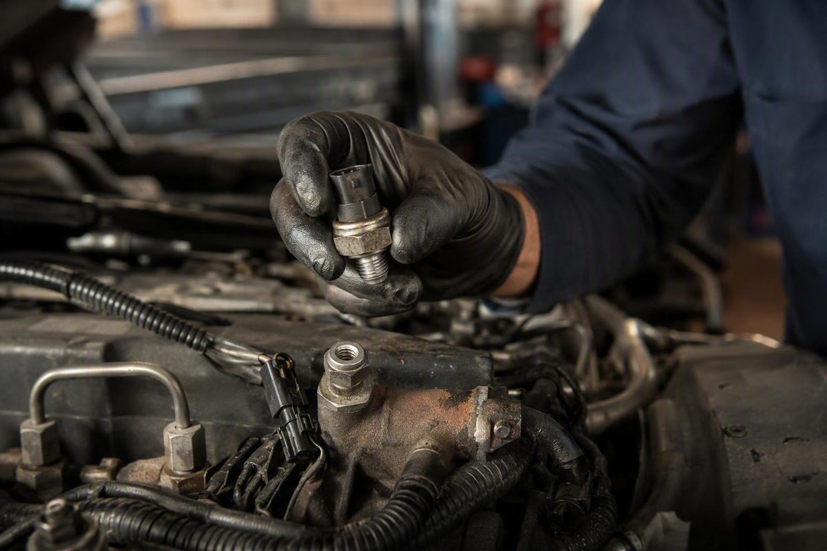
A biased sensor, poor connection or damaged signal circuit can make reported pressure differ from actual pressure.
What the injector control pressure sensor actually measures
On the 6.0L Powerstroke, ICP means Injection Control Pressure What Does the ICP Sensor Do on a 6.0 Powerstroke?. The injector control pressure sensor reports pressure in the engine’s high-pressure oil system, not pressure in a common-rail fuel system.
These engines use hydraulically actuated electronic unit injection, commonly called HEUI. High-pressure engine oil provides the hydraulic force needed to actuate the injectors. The ICP sensor converts pressure information into an electrical signal for the powertrain control module, or PCM.
In simplified form, the control loop works like this:
- The high-pressure oil pump supplies pressurized engine oil.
- The ICP sensor reports high-pressure oil-system pressure to the PCM.
- The PCM compares that feedback with the pressure it wants for the current operating condition.
- The PCM commands the Injection Pressure Regulator, or IPR, to adjust pressure.
- The ICP sensor reports the result so the PCM can continue correcting its command.
Commercial technical guidance for the 6.0L describes the ICP as a three-wire sensor supplied with a 5-volt reference and explains that the PCM uses its pressure feedback when controlling the IPR. It also identifies the measured pressure as high-pressure oil-rail pressure used to operate the HEUI injectors. These details are useful for understanding the system, but they are not a substitute for calibration-specific Ford service information. See the Bullet Proof Diesel explanation of 6.0L ICP operation.
The ICP sensor is therefore a feedback device. It does not create pressure, and it does not directly regulate pressure. That distinction produces three preliminary diagnostic categories:
- Inaccurate sensor: The sensor output is biased, implausible, intermittent, or otherwise fails an application-specific test.
- Electrical-circuit fault: The reference supply, ground, signal wire, connector, terminals, or previous wiring repairs compromise the signal.
- Actual pressure problem: The sensor may be reporting correctly while the high-pressure oil system fails to produce or maintain the required pressure.
These categories are a starting framework, not a complete diagnostic result. Plausible scan data and apparently sound wiring do not conclusively prove that the sensor is accurate. Definitively distinguishing biased feedback from actual hydraulic pressure may require factory pinpoint testing, validated comparison methods, or professional diesel diagnosis.
ICP sensor versus IPR valve: two different jobs
The ICP sensor and IPR valve work in the same control system, but they are not the same component.
The ICP sensor measures and reports pressure. The IPR valve regulates pressure under PCM command. In plain language, the ICP tells the PCM what the system appears to be doing; the PCM then uses the IPR to influence what happens next.
| Comparison | ICP sensor | IPR valve |
|---|---|---|
| Component type | Pressure-sensing electrical input | PCM-controlled pressure-regulating valve |
| Primary job | Reports high-pressure oil pressure | Regulates high-pressure oil pressure |
| PCM relationship | Sends feedback to the PCM | Receives commands from the PCM |
| Likely preliminary evidence | Missing, implausible, biased, or intermittent signal; connector or circuit concerns | Plausible but inadequate or unstable pressure; pressure that does not respond as expected during validated testing |
| Measures or regulates? | Measures | Regulates |
Their faults can look similar because both affect the same feedback loop. A biased ICP sensor can make pressure appear lower or higher than it really is. An IPR problem, weak pump, or hydraulic leak can make pressure genuinely low or unstable. Either condition may be accompanied by starting trouble, poor running, or questionable ICP data.
Do not replace the IPR merely because reported ICP is low. The sensor or circuit could be misreporting pressure. Conversely, do not replace the ICP sensor simply because the engine has a pressure-related complaint. It may be accurately reporting a hydraulic-system problem.
An owner-forum discussion also makes the practical distinction between the pressure-sensing ICP and the regulating IPR, while describing the unplug test and live-data review as preliminary checks. Because the discussion is user-generated and did not establish a confirmed repair, it should not be treated as factory diagnostic documentation. See the Ford Power Stroke Nation ICP-versus-IPR discussion.
7.3L versus 6.0L: locations, codes, and guidance that must stay separate
| Application | General ICP sensor location | Codes in the supplied commercial guidance | Important limitation |
|---|---|---|---|
| 7.3L Power Stroke | Near the front of the driver-side cylinder head and high-pressure oil rail; year and application details may vary | P1211 is associated with ICP-system problems. The same commercial guide reports a 725 PSI fallback value when the sensor is disconnected. ProSource Diesel’s 7.3L guide | Neither P1211 nor the reported fallback value proves sensor failure; the fallback figure is not verified here as a universal Ford specification |
| 2003–2004 6.0L Power Stroke | Behind the turbocharger | P2285, P2286, and P2287 | Location and code guidance must be verified for the exact vehicle and calibration |
| 2005–2007 6.0L Power Stroke | Near the front of the engine by the passenger-side valve-cover area | P2285, P2286, and P2287 | Do not apply the early-6.0L location automatically |
The 6.0L commercial source places the 2003–2004 sensor behind the turbocharger and the 2005–2007 sensor near the front passenger-side valve-cover area. It labels P2285 “circuit low,” P2286 “circuit performance,” and P2287 “circuit intermittent.” Because the evidence supplied here does not include authoritative Ford code documentation—and the P2286 shorthand should not be assumed authoritative—verify the exact code definition and diagnostic tree in application-specific service information before testing or replacing anything. The locations and vendor-supplied descriptions appear in the 6.0L ICP sensor guide.
For the 7.3L, P1211 should be treated as a reason to evaluate the ICP control system, not as proof that the ICP sensor failed. The code alone cannot identify which component is responsible.
Before testing or ordering a part, record:
- Engine displacement: 7.3L or 6.0L
- Vehicle model and model year
- Production date
- VIN or another exact application identifier
- Existing sensor location
- Connector shape and terminal arrangement
- Every stored, pending, and manufacturer-specific code
- The operating condition in which each complaint occurs
Do not transfer a 6.0L sensor location, test value, code description, tool recommendation, or part number to a 7.3L—or vice versa.
Symptoms and clues that justify testing—not immediate replacement
An ICP sensor or circuit problem may accompany:
- Hard starting
- Cranking without starting
- Rough or erratic idle
- Stalling
- Surging
- Misfires or vibration
- Reduced power
- Slow acceleration
- Poor fuel economy
- Implausible or unstable scan-tool pressure readings
These symptoms establish a reason to test, not a diagnosis.
Physical evidence and live data are generally more useful than symptoms alone. Oil in or around the ICP connector is a meaningful clue because it may indicate that oil has leaked through the sensor into the connector area. It is not universal proof that every sensor and pigtail must be replaced.
Connector condition matters independently of the sensor. Possible concerns include:
- Corroded or discolored terminals
- Weak terminal tension
- Pushed-back or damaged terminals
- Broken locking features
- Hardened, swollen, missing, or torn seals
- Brittle or chafed insulation
- Heat damage
- Oil migration into the harness
- Unsupported or poorly positioned wiring
- Corroded or low-quality previous splices
| Symptom or finding | Best preliminary check |
|---|---|
| Hard start or no-start | Record ICP data while cranking and inspect the sensor circuit and connector |
| Rough idle or stalling | Review reported pressure behavior and inspect for intermittent connector or wiring faults |
| Surging or power loss | Capture live data during the complaint when practical; note whether the signal changes smoothly or drops out |
| Oil at the connector | Assess the sensor for leakage and inspect terminals, seals, locks, and pigtail condition |
| Implausible pressure data | Verify the circuit using exact service information, while keeping an actual hydraulic problem in the diagnosis |
| A new sensor did not fix the complaint | Reconfirm fitment, inspect the connector again, and reassess the IPR, pump, leaks, injectors, and other systems |
Harness movement that coincides with a signal change is an observation worth recording, but it does not by itself identify the failed wire, terminal, connector, or sensor. A validated circuit test is still required.
If a newly installed ICP sensor does not correct the complaint, stop replacing sensors. Confirm that the installed part matches the application, preserve the current data, and return to the circuit and hydraulic system.
A test-first ICP diagnostic workflow
The following workflow is an orientation and preliminary-triage guide, not a complete factory diagnostic procedure. The supplied evidence does not provide authoritative pinouts, pressure requirements, code trees, torque values, or calibration-specific pass/fail criteria for every covered engine.
- Confirm the application and preserve the original evidence.
Identify the engine, model year, production date, and exact vehicle. Scan relevant modules and record stored, pending, and manufacturer-specific codes. Save available freeze-frame information and note whether the complaint occurs cold, hot, during cranking, at idle, or under load.
Record this information before clearing codes. The original operating context may help determine whether the problem appears continuous or intermittent.
- Inspect the sensor, connector, pigtail, and nearby wiring.
Look for:
- Oil inside or around the connector
- Corrosion or discoloration
- Loose, spread, damaged, or pushed-back terminals
- Broken locks
- Damaged or distorted seals
- Brittle insulation
- Chafing against brackets or engine components
- Heat exposure
- Unsupported wiring near the connector
- Previous splices or repairs
If harness movement coincides with a change in the complaint or scan reading, document it as a preliminary clue. Do not assume it identifies the sensor as the failed part.
- Review live ICP data under relevant operating conditions.
Where the scan tool and application support it, observe reported ICP during:
- Key on, engine off
- Cranking
- Initial start
- Idle
- Warm-up
- The condition that produces the complaint
Focus first on consistency and plausibility. Note readings that freeze, jump, disappear, or change at the same moment as the symptom.
Do not apply one universal pressure threshold across all 7.3L and 6.0L engines. The evidence available here does not establish factory minimum cranking pressure for every application.
- Compare related data without treating it as a conclusive component test.
If the scan tool and calibration expose desired ICP and IPR command or duty-cycle information, record those values together with reported ICP. This may help a qualified diagnostician understand the control system’s behavior.
However:
- Low reported ICP can be a false sensor or circuit signal.
- Low reported ICP can accurately reflect low hydraulic pressure.
- An IPR command value alone does not prove the IPR is defective.
- A pressure response does not conclusively validate sensor accuracy.
- A mismatch does not identify the leaking or weak component.
Without an application-specific diagnostic procedure, this comparison is observational rather than a definitive pass/fail test.
- Verify the circuit using exact service information.
The basic areas of interest are the sensor’s reference supply, ground, signal path, connector, and terminals. Use the wiring diagram, connector view, test equipment, and procedure specified for the exact engine and calibration.
This article does not provide pin locations or a probing method because those details are not established by the supplied evidence. If the correct service information or equipment is unavailable, have the circuit tested by a qualified diesel technician rather than improvising.
For the 6.0L only, the commercial Bullet Proof Diesel guide suggests approximately 0.2–0.25 volts with the key on and engine off and at least 0.8 volts while cranking. These are vendor-published values, not factory-verified specifications in the evidence available here, so do not use them as final pass/fail limits without confirming the exact application. See the commercial 6.0L voltage guidance.
- Use the unplug test only as supporting evidence.
Disconnecting the ICP sensor can cause the PCM to substitute fallback information. If starting or running changes, the result may support closer investigation of the sensor and circuit.
The result is not conclusive:
- Improvement does not prove the sensor is defective.
- No improvement does not clear the sensor.
- A start followed by an immediate stall is not a definitive result.
- The fallback strategy itself changes system operation.
The 725 PSI fallback figure reported for the 7.3L in the engine comparison above comes from a commercial guide. It is not established here as a factory specification applicable to every calibration.
- Classify the next diagnostic path without claiming certainty.
The preliminary evidence may support one of three directions:
- Sensor investigation: The output is implausible, intermittent, physically associated with leakage, or fails a validated application-specific test.
- Connector or wiring repair: Inspection or proper circuit testing identifies defective terminals, seals, wiring, reference, ground, or signal continuity.
- Further hydraulic diagnosis: The signal and circuit appear plausible, but required pressure is not being produced or maintained.
The third result does not prove the sensor is accurate. It means preliminary checks have not isolated it, and more authoritative testing is needed before opening or replacing high-pressure oil-system components.
When low ICP points beyond the sensor
A low ICP reading can mean two fundamentally different things.
First, the signal may be wrong. A biased sensor, poor connection, unstable reference, damaged signal circuit, contaminated connector, or loose terminal can make reported pressure differ from actual pressure.
Second, the signal may be correct. The sensor may be reporting inadequate high-pressure oil pressure associated with:
- IPR control or mechanical problems
- Insufficient high-pressure oil-pump performance
- Internal high-pressure oil leakage
- Sealing problems elsewhere in the hydraulic circuit
- Other injection-system faults
A pressure-related code identifies a circuit or control-system condition. It does not automatically name the failed part.
Use this preliminary decision tree:
- Is the signal fixed, erratic, intermittent, missing, or otherwise implausible?
- Yes: inspect and test the connector, terminals, reference, ground, signal circuit, and sensor using application-specific information.
-
No: continue.
-
Does the signal appear plausible while reported pressure remains inadequate?
- Yes: do not assume the sensor has passed. Confirm it through an approved diagnostic method, then move toward IPR, pump, and hydraulic-leak testing.
-
No: continue.
-
Does ICP behavior appear normal while the symptom remains?
- Yes: investigate other engine systems rather than forcing the complaint into an ICP diagnosis.
- No or uncertain: obtain better data and factory-level diagnostic information.
The supplied evidence does not establish:
- Factory minimum cranking pressure for every application
- Universal IPR duty-cycle limits
- Authoritative sensor pinouts
- A validated method for proving that plausible feedback is accurate
- Complete high-pressure oil-system test procedures
- Installation torque specifications
Do not invent those values or borrow them from a different engine, year, or calibration.
Invasive high-pressure oil-system diagnosis falls outside this preliminary guide. Use application-specific service procedures and appropriate equipment, or refer the vehicle to a qualified diesel diagnostician.
Most importantly, if one ICP sensor did not correct the complaint, installing another without new evidence is not a diagnostic strategy. Return to the signal, circuit, and hydraulic system.
Sensor, connector, or pigtail: deciding what actually needs replacement
Oil contamination at the ICP connector is a significant clue in the supplied 7.3L commercial guidance. The 6.0L guidance likewise recommends checking the pigtail for oil contamination, corrosion, and damaged wiring.
The sensor and pigtail are separate repair decisions.
Sensor replacement may be supported when:
- Oil is leaking through or from the sensor into the connector area
- The sensor fails a validated application-specific test
- Output remains implausible after the circuit has been properly checked
- The sensor is physically damaged
Pigtail repair or replacement may be supported when:
- Terminals are corroded, loose, spread, burned, or pushed back
- The connector lock no longer holds securely
- Seals are torn, swollen, hardened, or missing
- Wiring is brittle, chafed, heat-damaged, or oil-saturated
- Previous splices are corroded or poorly supported
- Oil migration has compromised terminal or wire condition
Use this inspection checklist:
- [ ] Check each terminal for corrosion and discoloration.
- [ ] Verify terminal retention and condition.
- [ ] Confirm that the connector lock engages.
- [ ] Inspect seals for swelling, tears, hardening, or absence.
- [ ] Flex nearby insulation gently and look for cracking.
- [ ] Examine previous splices for corrosion and strain.
- [ ] Check how far oil has migrated into the harness.
- [ ] Look for chafing and heat exposure.
- [ ] Confirm that the connector matches the replacement sensor.
Cleaning oil from an otherwise sound connector may be part of a repair, but cleaning alone will not stop a sensor that continues to leak. It also cannot restore damaged terminals, a broken lock, failed seals, or deteriorated wiring.
Replacement packages differ. A sensor-only package assumes that the original connector remains serviceable. A kit containing a pigtail provides parts for connector repair when inspection supports it. As one example, Mishimoto lists model MMSN-F2D-97ICP for specified 7.3L applications as containing one sensor, one wiring pigtail, and three butt connectors. Fitment, performance, quality, and warranty statements on that page are manufacturer claims and require application confirmation. See the Mishimoto kit listing.
If the pigtail requires replacement, follow application-specific service information for conductor size, splice type, sealing, routing, and strain relief. This article does not establish a universal wiring-repair method for every engine compartment and connector.
Replacement basics and fitment checks before ordering
ICP replacement access and specifications vary by engine, model year, sensor location, and vehicle packaging. The supplied evidence supports only a general outline, not a complete factory procedure.
Before disassembly, obtain the application-specific instructions and final torque specification. A commercial 7.3L replacement guide calls for disconnecting the negative battery cables, releasing the connector, removing the sensor, keeping contamination out of the oil passage, lubricating the replacement O-ring with clean oil, and avoiding overtightening. It also reports that original and replacement sensor bodies may use different hex sizes. Consult the ProSource Diesel 7.3L replacement outline, then verify the procedure against service information for the actual vehicle.
A general replacement outline is:
- Confirm the diagnosis and replacement part before disassembly.
- Obtain the correct application-specific procedure and torque specification.
- Allow appropriate access and follow the specified battery-disconnection procedure.
- Clean the work area before opening the oil passage.
- Release the electrical connector by its locking feature.
- Verify the tool required by the sensor actually installed.
- Remove the sensor according to the application procedure.
- Protect the exposed oil passage from contamination.
- Compare the old and new sensor, including connector, threads, seal, body shape, and clearance.
- Lubricate the new O-ring only as directed for the application and part.
- Start the sensor carefully and tighten it to the specified value.
- Reconnect and route the harness as specified.
- Restore the electrical system according to the service procedure.
- Check for leakage, codes, and live-data behavior under the original complaint conditions.
Do not guess at torque or assume that one socket fits every original and replacement sensor. The available evidence documents differing sensor-body sizes in commercial guidance and retailer feedback, but it does not establish a universal tool or installation specification.
Pre-purchase fitment checklist
Before ordering, confirm:
- [ ] 7.3L or 6.0L engine
- [ ] Model year
- [ ] Production date
- [ ] Exact vehicle model and configuration
- [ ] VIN-specific catalog fitment where available
- [ ] Existing sensor location
- [ ] Connector shape and terminal arrangement
- [ ] Sensor thread and physical design
- [ ] Clearance around the sensor body
- [ ] Sensor-only or sensor-and-pigtail package
- [ ] Included seals, wiring parts, or hardware
- [ ] Confirmed catalog or manufacturer part number
- [ ] Stated warranty and return conditions
Retailer and marketplace numbers are useful search leads, not authoritative supersession records.
One marketplace listing claims a 1999–2003 7.3L application and lists F4TZ-9F838-A, F6TZ-9F838-A, 1807329C92, ICP102, and 1807329CP2 as replacement references. The listing does not provide complete VIN-specific compatibility, so each number requires independent confirmation. See the marketplace 7.3L sensor listing.
A separate retailer lists Ford YC3Z-9F838-A for specified 1997–2003 7.3L applications beginning with a stated production date of January 1, 1997. It shows a separate listing for 1994–1996 applications. Treat the retailer’s Ford ICP listing as a catalog lead rather than complete fitment authority.
Keep uncertain shopping examples separated by engine. The Standard Ignition ICP101K page references 4C3Z9F838AK, but the supplied page does not establish exact compatibility without vehicle selection. It should not be inferred to be another 7.3L option merely because it appears in a general ICP search. Use the O’Reilly ICP101K listing only as a starting point for vehicle-specific catalog lookup.
When comparing OEM and aftermarket choices, rely on verifiable attributes:
- Confirmed application
- Connector configuration
- Catalog number
- Sensor-only or kit contents
- Included pigtail or hardware
- Stated warranty
- Seller and return channel
Marketing terms such as “direct fit” or “OE equivalent” do not prove equal calibration, accuracy, durability, or service life. The supplied evidence also does not support a blanket claim that every OEM sensor is superior to every aftermarket product.
Avoid choosing solely by an online price, rating, or review. Prices, inventory, sellers, warranties, ratings, and return terms can change. Correct fitment and a supported diagnosis matter more.
Frequently asked questions
Does an injector control pressure sensor measure fuel pressure?
No. On the covered 7.3L and 6.0L Power Stroke HEUI systems, the ICP sensor reports pressure in the high-pressure engine-oil system. That oil pressure supplies the hydraulic force used to actuate the injectors. The ICP is not a common-rail fuel-pressure sensor.
Is the ICP sensor the same as the IPR valve?
No. The ICP sensor measures and reports pressure. The IPR is a PCM-controlled valve that regulates pressure. Their faults can produce overlapping symptoms because both components participate in the same control loop.
Will unplugging the ICP sensor prove that it is bad?
No. Unplugging the sensor may cause the PCM to substitute fallback information. Better starting or running is a useful clue, not proof of sensor failure. No change—or a start followed by an immediate stall—also requires continued diagnosis.
Does oil in the ICP connector mean the pigtail must be replaced?
Not automatically. Oil at the connector may support a leaking-sensor diagnosis, but the pigtail decision depends on terminal condition, tension, seals, locking features, insulation, oil migration, and wiring condition. A mechanically sound connector may remain serviceable; a damaged connector should not be reused simply because it was cleaned.
Which trouble codes are associated with the 7.3L and 6.0L ICP systems?
The supplied commercial 7.3L guidance associates P1211 with ICP-system problems, while the supplied 6.0L guidance discusses P2285, P2286, and P2287. Those code references are summarized in the engine-specific table above. Do not treat the vendor descriptions as authoritative definitions or as proof of a failed sensor; verify each code and diagnostic procedure for the exact vehicle in Ford service information.
The practical rule is straightforward: identify the engine first, preserve the original codes and data, inspect the sensor connector and wiring, and evaluate engine-specific live data without inventing universal thresholds. Use the unplug test only as supporting evidence. Replace the sensor or pigtail only when inspection and validated testing support that decision. If the signal appears plausible—or replacement changes nothing—move the diagnosis toward the IPR and broader high-pressure oil system rather than continuing to swap parts.