
How to Identify and Diagnose the Right ICP Sensor on a 6.0L Power Stroke
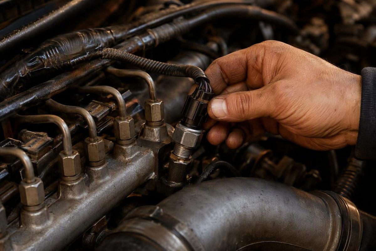
Identify the installed setup, inspect the connector and harness, then record actual and desired ICP, ICP voltage and IPR command when the fault appears.
A suspected injector control pressure sensor fault on a 6.0L Power Stroke raises two separate questions:
- Is the ICP sensor—or its connector and wiring—actually faulty?
- Which early or late sensor configuration is installed on this engine?
Neither question should be answered from symptoms or model year alone. Hard starting, crank-no-start, rough idle, stalling, surging, power loss, and low indicated ICP can result from an inaccurate electrical signal or genuinely inadequate high-pressure oil. Fitment is also easy to misidentify because retailer descriptions disagree about the transition during the 2004 model year.
The safest approach is to identify the installed configuration physically, inspect the connector and harness, and record actual ICP, desired ICP, ICP voltage, and IPR command under the conditions that reproduce the complaint. Buy a sensor or pigtail only after those checks point toward a fault and a VIN- or engine-specific catalog confirms the application.
What the ICP sensor does in the 6.0L Power Stroke HEUI system
ICP means injection control pressure. The 6.0L Power Stroke uses a hydraulically actuated electronic unit injection, or HEUI, system. High-pressure engine oil supplies the hydraulic force used to actuate the injectors.
Four components are central to this pressure-control system:
- High-pressure oil pump (HPOP): Supplies high-pressure engine oil.
- ICP sensor: Reports pressure in the high-pressure oil system.
- Injection Pressure Regulator (IPR): Regulates pressure by controlling oil flow or pressure bleed-off.
- Powertrain Control Module (PCM): Compares reported pressure with desired pressure and adjusts the IPR command.
The ICP sensor is a three-wire sensor supplied with a 5-volt reference. It returns an analog voltage representing high-pressure oil-system pressure. The PCM interprets that signal as actual ICP, compares actual with desired ICP, and modulates the IPR to reduce the difference. ICP-related information also contributes to injection management, but the sensor does not independently control every aspect of fuel delivery. Bullet Proof Diesel describes the three-wire circuit and the sensor’s relationship with the PCM and IPR.
The system operates as a feedback loop:
- The PCM calculates desired ICP for the operating condition.
- The sensor reports actual ICP.
- The PCM adjusts IPR command to move actual pressure toward desired pressure.
- The sensor reports the result, allowing control to continue.
This distinction is critical during diagnosis. A biased sensor can falsely report low pressure and make scan data resemble a hydraulic failure. Conversely, a healthy sensor can accurately report low pressure caused by a weak HPOP, an IPR problem, or an internal oil leak.
That is why ICP data should be evaluated with desired ICP, ICP voltage, and IPR command. One pressure reading cannot reveal whether the sensor is inaccurate, the regulator cannot respond, or the hydraulic system cannot generate or retain pressure.
Early versus late ICP sensor location: identify the configuration before ordering
The 6.0L uses two general ICP sensor configurations. Retailer descriptions commonly divide them at either 2004.5 or 2005, so a model-year label is not a dependable production breakpoint.
| General application period | Physical location | Retailer-reported reference | Verification warning |
|---|---|---|---|
| Early, generally described as 2003–2004 | Behind the turbo, near or at the top of the HPOP cover | 3C3Z-9F838-AA | Do not assume every 2004 vehicle uses this version |
| Late, generally described as 2004.5–2007 | In or near the front passenger-side valve-cover area | 4C3Z-9F838-A | Confirm the installed location and mounting design before ordering |
These periods and part numbers are retailer-provided references, not an official Ford production-breakpoint or supersession record. DIESELSITE divides the applications into an early 2003–2004 top-of-HPOP-cover version and a later 2004.5–2007 in-valve-cover version. Another commercial technical guide simplifies the location split to 2003–2004 and 2005–2007. The DIESELSITE listing shows its two location-based configurations and associated cross-references.
The sources therefore agree about the existence and physical locations of the two configurations, but they do not establish an authoritative date or serial-number breakpoint.
Early configuration
The early ICP sensor is generally located behind the turbo, at or near the top of the high-pressure oil-pump cover. Access is normally more restricted than it is with the later configuration.
That does not establish that turbo removal is always required—or that it can always be avoided. Access depends on the vehicle, installed components, available tools, and the approved service procedure. Identify the configuration and obtain current model-specific service information before deciding how much disassembly is necessary.
Late configuration
The later sensor is generally found in or near the front passenger-side valve-cover area. It is typically easier to see and reach than the early behind-the-turbo sensor.
Even so, compare the original sensor, connector, flange, and mounting point directly with the proposed replacement.
Identification sequence
Use this sequence before ordering an injector control pressure sensor for a 6.0L:
- Record vehicle information. Note the VIN, build date, engine information, and any available engine serial information.
- Physically locate the existing sensor. Determine whether it is behind the turbo at the HPOP-cover area or near the passenger-side valve cover.
- Inspect the mounting and connector. Compare the connector shape, locking features, sensor body, flange, and mounting arrangement.
- Check for previous work. A replacement engine, modified harness, or earlier conversion can make the body’s model year misleading.
- Confirm the application. Use an authoritative parts catalog or a supplier willing to check the VIN, engine information, and physical configuration.
- Confirm package contents. Determine whether the listing is for a sensor, a sensor-and-pigtail kit, or a connector alone.
Build information is useful only when checked against a qualified catalog or supplier. This evidence does not establish a dependable date or serial-number breakpoint that owners can apply by themselves.
If you have a 2004 truck, do not order until you have physically located the sensor. A listing that merely says “fits 2004” is not enough.
Use similar caution with vehicle-line claims. Retailer descriptions for Excursion applications vary, while marketplace sellers may extend certain parts to Econoline years without explaining production revisions. A search-result match does not establish compatibility with a particular F-Series, Excursion, or Econoline.
Symptoms and codes that justify testing—not immediate replacement
An ICP sensor or circuit problem may be associated with:
- Hard starting
- Crank-no-start
- Rough or erratic idle
- Stalling
- Surging
- Power loss or poor response under load
- Implausible, low, or unstable scan-tool pressure readings
Commercial technical guidance also mentions poor fuel economy and black smoke. Those symptoms are especially nonspecific and should not be treated as dependable evidence of ICP sensor failure.
Codes frequently discussed in connection with the ICP circuit include P2285, P2286, and P2287. Confirm the exact description and diagnostic path in current Ford service information before testing the circuit. The important practical point is that an ICP-related circuit code implicates the signal path, not automatically the pressure-sensing element.
Possible electrical causes include:
- Oil contamination
- Poor terminal contact
- A damaged pigtail
- An open or shorted wire
- A reference-voltage fault
- A ground fault
- Another problem affecting the reported signal
Why the symptoms overlap
| Complaint or evidence | Possible ICP signal or circuit cause | Other systems that can produce similar evidence |
|---|---|---|
| Crank-no-start | Biased signal, open circuit, contaminated connector | IPR fault, weak HPOP, high-pressure oil leak, low base oil pressure, FICM or synchronization issue, inadequate fuel supply |
| Hard hot restart | Heat-sensitive sensor, wiring, or terminal fault | High-pressure oil leak that worsens as oil heats, IPR fault, HPOP problem |
| Rough or unstable idle | Intermittent signal or poor terminal contact | Sticky IPR, injector issue, fuel-pressure problem, FICM fault |
| Stalling or surging | Signal dropout or implausible pressure change | IPR instability, other wiring fault, fuel-delivery problem, real hydraulic fluctuation |
| Power loss under load | Under-reporting or unstable sensor signal | HPOP capacity problem, internal oil leak, fuel-pressure loss, injector or air-management fault |
| Low actual ICP | Biased sensor output | Genuine inability to generate or retain high-pressure oil |
| Erratic ICP | Sensor, terminal, or harness intermittency | Sticky IPR, oil-system debris, real pressure instability |
Symptoms should define when and how to test, not which part to buy. If the problem occurs only during the first cold start, record data then. For a hot no-start, test immediately after the engine reaches the failing condition. If it stumbles only under load, capture the relevant parameters under that load rather than relying on an idle check.
An unresolved 2003 acceleration-stumble case illustrates the risk of parts swapping. The owner reported replacing the ICP sensor, IPR, HPOP, seals, and several other components, but the stumble remained. The remote discussion ended without a confirmed cause, and the reported measurements were not independently verified. Its limited lesson is still useful: replacing pressure-system parts does not prove the original fault was in that system. The JustAnswer case records the reported repair history and unresolved result.
A test-before-replacement workflow for the ICP sensor and circuit
A sound workflow begins outside the ICP circuit. For a crank-no-start or major drivability complaint, verify the operating fundamentals before interpreting one pressure parameter.
1. Check basic operating requirements
Inspect or verify:
- Engine-oil level and condition
- Adequate cranking behavior and battery condition
- Base oil-pressure indication while cranking
- Fuel supply and filter condition
- FICM power
- Cam/crank or FICM synchronization where supported by the scan tool
- Disconnected, damaged, or recently disturbed wiring
The HEUI system depends on engine oil. Low oil, deteriorated oil, or a base-pressure problem can prevent the high-pressure system from operating correctly. Fuel, FICM, synchronization, and cranking faults can also cause a no-start even when ICP data initially attracts attention.
2. Retrieve codes and freeze-frame data
Retrieve active, pending, and history codes from the modules available to the diagnostic equipment. Record freeze-frame information where available.
Treat this as general diagnostic practice rather than proof of an ICP fault. The presence of an ICP-related code does not justify automatic sensor replacement, while the absence of a code does not eliminate a biased sensor, intermittent connector fault, or hydraulic-pressure problem.
3. Record the relevant live data together
Use a scan tool capable of displaying at least:
- Actual ICP
- Desired ICP
- ICP sensor voltage
- IPR duty cycle or command
For a no-start, record the values key-on/engine-off and throughout cranking. For a drivability complaint, capture them during the cold start, hot restart, idle instability, acceleration, or load condition that produces the symptom.
Look for:
- Whether ICP voltage is stable before cranking
- Whether actual ICP rises smoothly
- Whether actual pressure follows desired pressure
- How aggressively the PCM commands the IPR
- Whether signal dropouts correspond with the complaint
- Whether behavior changes as oil temperature rises
Do not focus only on the highest pressure displayed. The relationship among the parameters is more informative than one isolated number.
4. Evaluate KOEO voltage cautiously
One independent diesel diagnostic guide gives approximately 0.16–0.28 volts KOEO, at normal temperature after the engine has been shut off for at least two minutes. Oregon Fuel Injection provides that range and test context in its 6.0L diagnostic guide.
A commercial sensor guide gives a narrower, overlapping range of approximately 0.20–0.25 volts KOEO. That vendor’s testing guidance states the narrower range.
These are third-party diagnostic ranges, not universal Ford specifications for every calibration and production revision. A stable reading in the overlapping area is encouraging, but it does not prove that the sensor remains accurate under pressure. A substantially biased, unstable, or implausible engine-off reading deserves circuit and sensor investigation.
5. Watch voltage and pressure during cranking
Approximately 0.8 volts while cranking is commonly presented in third-party guidance as a value associated with enough pressure for starting. Treat that number only as a diagnostic clue, not a universal Ford threshold.
Cranking data can vary with:
- Oil temperature
- Battery condition
- Starter performance
- Calibration
- Production revision
- Scan-tool update rate
- The point during cranking at which the value is sampled
For the same reason, unsupported universal idle or loaded-pressure targets are unhelpful. Compare actual with desired ICP and interpret the IPR response rather than condemning a component from one number.
6. Perform an unplugged-ICP comparison when appropriate
Disconnecting the ICP sensor causes the PCM to use a substituted strategy instead of the live sensor signal. If starting or operation improves with the sensor unplugged, the connected signal may be misleading the PCM.
That result does not conclusively prove that the sensor element has failed. Disconnecting it changes the control strategy and removes the complete signal circuit from normal operation. Improvement directs attention toward the sensor, connector, and wiring, but the result must still be reconciled with live data, terminal condition, circuit tests, and hydraulic evidence.
Use this only as a temporary comparison test—not as a permanent operating arrangement or a substitute for diagnosis.
When to stop
Seek qualified help if you lack:
- A scan tool that displays actual ICP, desired ICP, voltage, and IPR command
- Current service information for the exact configuration
- Reliable circuit pinouts and electrical procedures
- Confidence identifying or accessing the early behind-the-turbo sensor
- The tools and training needed to evaluate the high-pressure oil system
A generic code reader and symptom list cannot reliably distinguish an electrical ICP fault from a hydraulic no-start.
Inspect the pigtail, terminals, and harness before condemning the sensor
Inspect it before ordering parts and again before connecting a replacement sensor.
Connector and harness checklist
Look for:
- Oil inside the connector
- Corrosion, moisture, or debris
- Loose, recessed, bent, or spread terminals
- Weak terminal tension
- A cracked connector body
- A broken or ineffective locking tab
- Damaged seals
- Brittle, melted, cut, or oil-saturated insulation
- Harness chafing against nearby components
- Stretched wires near the connector
- Poor splices or unsupported previous repairs
- Wiring disturbed during turbo, valve-cover, HPOP, or nearby work
Oil in the connector is a meaningful clue. It may indicate that the sensor has leaked internally and contaminated the pigtail. Oil and degraded terminal contact can interfere with the signal, but contamination alone does not prove that the sensor caused every reported symptom.
A reviewer on a later-sensor retailer page reported that the pigtail, rather than the sensor, was the actual problem. That individual experience is not a failure-rate study, but it reinforces the value of inspecting the connection before replacing the sensor. The retailer page includes that connector-related customer report.
Installing a new sensor while reusing oil-soaked seals, weak terminals, corrosion, or damaged wiring can leave the original fault unresolved.
Third-party diagnostic guidance recommends replacing both the sensor and pigtail when the sensor is leaking oil. Apply that recommendation to the observed condition rather than automatically replacing both parts whenever a trace of oil appears. Pigtail replacement becomes more persuasive when:
- Terminal tension is unreliable.
- Seals or the connector body are damaged.
- Contamination cannot be removed adequately.
- Oil has migrated into the wire insulation.
- The locking mechanism no longer holds securely.
- Circuit testing confirms an intermittent connection.
Do not infer terminal functions from an unverified online diagram. Use model-specific service information for pin identification, reference-voltage testing, signal-circuit checks, ground testing, and any resistance or voltage-drop procedure. The available evidence does not establish one Ford-validated pinout for every 6.0L revision.
Separate these three diagnostic patterns:
- Stable but implausible signal: Investigate sensor bias, reference voltage, signal wiring, ground quality, and scan-data plausibility.
- Intermittent signal: Inspect terminal tension, connector locking, harness movement, chafing, and heat- or vibration-related faults.
- Stable, believable low-pressure signal: Compare desired ICP with IPR command, then determine whether the hydraulic system is genuinely failing to generate or retain pressure.
How to distinguish a bad ICP signal from a real high-pressure oil problem
No single pattern proves one failed component. Combining actual ICP, desired ICP, IPR command, signal stability, connector condition, and the unplugged-sensor comparison can establish a more useful diagnostic direction.
| Observed pattern | Likely direction | Recommended follow-up |
|---|---|---|
| KOEO voltage is biased or unstable before cranking | Sensor or circuit concern | Inspect the connector and test reference, signal, and ground with correct service information |
| Actual ICP is implausible, the signal is erratic, and the connector is oily or damaged | Sensor or pigtail concern becomes stronger | Repair confirmed connector faults and verify the signal again |
| Engine improves with ICP unplugged | The connected signal or circuit may be misleading the PCM | Test the sensor and wiring; do not assume the sensor alone is responsible |
| Actual ICP remains below desired while IPR command approaches its upper limit | The system may be unable to build or retain pressure | Confirm signal accuracy, then investigate the IPR, HPOP, and internal leakage |
| Actual and desired ICP track normally but the symptom remains | ICP may not be the primary cause | Expand diagnosis to fuel, FICM, synchronization, injectors, air management, and related systems |
| Actual ICP drops abruptly while voltage or harness movement is erratic | Electrical intermittency is possible | Test the connector and harness under the conditions that trigger the dropout |
| Actual ICP changes smoothly but remains genuinely low | A hydraulic problem becomes more likely | Test pressure generation, regulation, and internal leakage |
The most important hydraulic pattern is actual ICP remaining below desired ICP while the PCM drives IPR command toward its upper limit. The PCM is asking the regulator to retain more pressure, but reported pressure still does not reach the target. Once signal credibility has been established, diagnosis should expand beyond the sensor.
Possible hydraulic causes supported by third-party diagnostic guidance include:
- A sticking or contaminated IPR
- A weak HPOP
- Injector-related high-pressure oil leaks
- Leaking standpipes
- Rail-plug leaks
- A high-pressure-pump connection leak
- An STC fitting problem on applicable later engines
- Other internal high-pressure oil leaks
Erratic ICP does not automatically point back to the sensor. A sticky IPR, debris in the oil system, or a real leak that changes with temperature or operating conditions may also cause unstable pressure.
One diagnostic guide provides two bounded cranking examples:
- Approximately 0.4–0.5 volts with IPR at 85% is presented as a possible stuck-IPR pattern.
- Approximately 0.6–0.7 volts with IPR at 85% is presented as a likely high-pressure-leak pattern.
The same guide cautions through its diagnostic context that these are troubleshooting indicators rather than component verdicts. Sensor error, oil temperature, pump condition, test conditions, and simultaneous faults can change the interpretation. Oregon Fuel Injection provides the voltage examples, upper-command context, and leak-testing cautions.
High-pressure air testing can help locate an internal leak, but it is not a casual next step. It requires the correct model-specific tooling and service information, and the IPR must be held closed to isolate the high-pressure system. If the test is configured incorrectly, air may escape into the crankcase instead of isolating the leak path, producing misleading results.
Do not improvise a step-by-step air-test procedure. Escalate the vehicle to a qualified 6.0L technician when:
- Actual ICP remains persistently low while IPR command is high.
- Electrical testing does not establish whether the signal is valid.
- High-pressure leak testing is required.
- Early-model sensor access requires substantial disassembly.
- The result changes with temperature but cannot be reproduced safely.
- Multiple systems or previous repairs have complicated the evidence.
Part numbers and buying criteria for an early or late 6.0L ICP sensor
Part-number searches are useful for identifying candidates, but they do not establish official interchangeability. Treat the following as source-labeled commercial references rather than a definitive Ford or International catalog.
| Number | How it is listed | Claimed configuration or application | Important caveat |
|---|---|---|---|
| 3C3Z-9F838-AA | DIESELSITE retailer cross-reference | Early 2003–2004 top-of-HPOP-cover configuration | Retailer reference; not proof of every 2004 application |
| 4C3Z-9F838-A | DIESELSITE and marketplace reference | Later 2004.5–2007 valve-cover configuration | Verify physical location, VIN, engine information, and mounting design |
| 3C3Z-9F838-EA | Marketplace listing | Ford-branded early-type search result | The listing does not establish an official supersession relationship |
| 1845428C92 | Marketplace cross-reference | Referenced by some aftermarket sellers | Seller-provided cross-reference; not independently verified |
| AP63450 | KC Turbos listing for an Alliant sensor | Described as a stock direct-fit replacement for 2004–2007 applications | The listing does not resolve the transition by build or sensor location |
KC Turbos identifies Alliant AP63450 as a stock replacement for the applications listed on its page, using a broad 2004–2007 description. Because the listing does not distinguish the transition by physical location or engine build, it should not override what is installed on the vehicle. The KC Turbos listing provides the retailer’s stated AP63450 application.
Marketplace search results introduce additional uncertainty. They mix Ford-branded sensors, aftermarket sensors, sensor-and-pigtail kits, and connector-only products. Listings also reference 3C3Z-9F838-EA and 1845428C92 without establishing an official Ford or International supersession chain. The Amazon search snapshot illustrates the mixed product types and seller-provided cross-references.
Understand what is being sold
- Sensor only: Suitable only if the existing connector and harness are serviceable.
- Sensor-and-pigtail kit: Includes a sensor and replacement connector with wire leads; both must fit the engine and circuit.
- Connector or pigtail only: Repairs the harness connection but does not replace a leaking or electrically faulty sensor.
- Repair harness with accessories: May include seals, terminals, splices, or insulators; inspect the actual contents.
A product image showing a connector beside a sensor does not prove that both are included. Read the package description and verify each component.
Buyer checklist
Before purchasing, confirm:
- Early HPOP-cover or later valve-cover configuration
- VIN, engine build, or engine serial applicability through an authoritative catalog
- Sensor body, connector keying, flange, and sealing design against the original
- Whether the package is sensor-only, sensor-and-pigtail, or connector-only
- Seller identity and reputation
- Part authenticity and traceable packaging
- Warranty terms
- Return policy if the part does not match
- Included seals, connector components, and hardware
- Whether pigtail repair is part of the job
- Total installed cost, including access labor and diagnostic time
The supplied marketplace snapshot showed budget sensors priced below Ford-branded and established aftermarket products, some of which were listed above $100. Those displayed prices were time-sensitive and do not establish calibration accuracy, durability, or fitment.
Do not rank sensors solely by price, star ratings, small review samples, or seller language such as “OEM-equivalent” or “best.” The correct physical configuration from a traceable seller with useful warranty and return terms is a better starting point than either the cheapest or most expensive search result.
Replacement boundaries and post-repair verification
The available evidence supports configuration identification and diagnosis. It does not establish a complete installation procedure, official torque specification, sealing method, or connector pinout. Obtain current service information for the exact engine before removal.
Keep the configurations separate. The early behind-the-turbo sensor may require substantially more access work than the later passenger-side valve-cover version. Do not assume turbo removal is always required, and do not assume it can always be avoided.
Before installation:
- Compare the new and original sensors side by side.
- Confirm that the connector keys and locking mechanism match.
- Confirm that the body, threads, flange, and mounting arrangement match.
- Inspect the pigtail and harness instead of transferring a known electrical fault to the new sensor.
- Follow model-specific instructions for removal, sealing, and tightening.
- Route repaired wiring away from heat, abrasion, and moving components.
Do not improvise a torque value, apply an unverified sealing product, or assume a generic connector diagram applies. Likewise, do not perform a code-clearing, adaptive-reset, or PCM procedure merely because a general aftermarket instruction says it is universally required.
Post-repair checklist
After replacing the sensor, repairing the connector, or completing another confirmed repair:
- Inspect the connection. Verify full engagement, lock retention, terminal seating, and proper harness routing.
- Recheck codes. Distinguish stored history codes from faults that return during testing.
- Check KOEO stability. Confirm that engine-off voltage is stable and plausible for the test conditions.
- Compare actual and desired ICP. Watch both during cranking, idle, and the original failure condition.
- Monitor IPR command. Confirm that pressure behavior and regulator command make sense together.
- Repeat the original test. Recreate the cold start, hot restart, unstable idle, or load condition that produced the complaint.
- Road-test safely. Operate the vehicle under the same safe conditions that previously produced the symptom.
- Reinspect the repair. Check for leakage, connector movement, or harness contact after heat and vibration have been introduced.
Subjective improvement is useful but weaker than improvement accompanied by stable live data and corrected actual-versus-desired ICP behavior.
If ICP remains low or erratic, return to electrical and hydraulic diagnosis. Installing another sensor, IPR, HPOP, or set of injectors without confirming the next fault repeats the parts-swapping problem.
Frequently asked questions
Where is the ICP sensor on a 2004 6.0 Power Stroke?
A 2004 vehicle may have the early sensor behind the turbo near the top of the HPOP cover or the later-style sensor near the passenger-side valve-cover area. Retailers describe the transition differently, so model year and build date alone are not definitive.
Physically locate the existing sensor, compare its connector and mounting design, and confirm the application through a VIN- or engine-specific catalog before ordering.
What should the 6.0L ICP sensor read with the key on and while cranking?
Third-party guidance gives approximately 0.16–0.28 volts KOEO after the engine has been off for at least two minutes. Another commercial guide gives an overlapping range of approximately 0.20–0.25 volts. Approximately 0.8 volts while cranking is also commonly presented as starting-related guidance.
These values are not universal Ford specifications. Evaluate signal stability, actual versus desired ICP, and IPR command while accounting for oil temperature, cranking performance, calibration, production revision, and test conditions.
Will a 6.0 Power Stroke run with the ICP sensor unplugged?
The PCM can use a substituted strategy when the ICP sensor is disconnected, so the engine may start or operate differently.
Improvement suggests that the connected ICP signal or circuit may be misleading the PCM, but it does not conclusively prove that the sensor element has failed. Inspect the pigtail and wiring, review scan data, and determine whether the hydraulic system can generate and retain pressure.
Does oil in the ICP connector mean I need both a sensor and a pigtail?
Oil in the connector is a meaningful indication that the sensor may be leaking and the pigtail may be contaminated. Inspect the terminal tension, corrosion, seals, insulation, and the extent of oil migration.
Replacing both becomes reasonable when the sensor is leaking and the connector cannot be restored to dependable mechanical and electrical condition. Oil alone does not prove that both parts caused every symptom.
Do P2285, P2286, and P2287 prove the ICP sensor is bad?
No. These codes are associated with the ICP signal circuit, but they do not prove that the sensing element has failed. The connector, terminals, wiring, reference supply, ground, or another condition affecting the signal may be responsible.
Commercial descriptions of the individual codes are not consistently reliable—particularly for P2286—so use current Ford service information for the exact code definition and test path. Diagnose the complete circuit and compare actual ICP with desired ICP and IPR command before replacing the sensor.
The final decision path is simple: physically identify the early or late configuration, inspect the sensor connector and harness, test the ICP signal under the original failure condition, evaluate actual ICP alongside desired ICP and IPR command, and investigate real high-pressure oil loss when the data points beyond the electrical circuit. Buy only after fitment is verified, then validate the repair with stable scan data and reproduction of the original operating condition.