
How to Diagnose a Suspected 7.3L Power Stroke ICP Sensor Before Replacing It
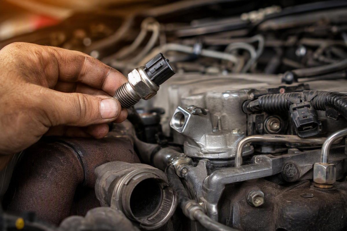
Diagnosis starts with sensor and connector inspection, codes and cranking RPM, then compares reported ICP, commanded ICP and IPR duty cycle.
A suspected injector control pressure sensor fault on a 7.3L Power Stroke can cause hard starting, rough running, stalling, surging, and power loss. Those complaints can also result from damaged wiring, an injection pressure regulator fault, leaking seals, unsuitable engine oil, missing engine-speed input, or a high-pressure oil pump that cannot produce the requested pressure.
That overlap makes injector control pressure sensor 7.3 diagnosis a test-first job. The scan-tool parameter commonly labeled “actual ICP” is derived from the sensor signal; it is not an independent mechanical measurement. A low reading can therefore mean either that the signal is wrong or that the engine genuinely lacks high-pressure oil.
The framework below is based primarily on commercial diesel-diagnostic guidance, seller documentation, and product listings. It is not a Ford workshop-manual procedure. Use vehicle-specific service information for authoritative specifications, wiring diagrams, torque values, circuit tests, and high-pressure oil-system procedures.
The practical approach is to inspect the sensor and connector, retrieve codes, confirm engine speed during cranking, and compare reported ICP with commanded ICP and IPR duty cycle. Replace the sensor only when leakage, circuit findings, or live data make it a reasonable suspect.
What the 7.3L ICP sensor does
ICP is expanded as both Injection Control Pressure and Injector Control Pressure in commercial parts and diagnostic literature. Both terms refer to pressure feedback from the 7.3L Power Stroke’s hydraulically actuated electronic unit injector, or HEUI, system.
The HEUI system uses pressurized engine oil to actuate injection. The ICP sensor monitors pressure in that high-pressure oil circuit and reports it to the powertrain control module, or PCM.
The PCM compares ICP feedback with the pressure target for the current operating condition. It then commands the injection pressure regulator, commonly called the IPR, to control high-pressure oil output. A commercial 7.3L ICP guide describes this sensor, PCM, and IPR relationship, although its procedures should not replace application-specific Ford service information.
That control loop creates two distinct diagnostic possibilities:
- False or unreliable feedback: The oil system may be producing usable pressure, but a defective sensor, damaged connector, poor terminal contact, or wiring fault reports the wrong value.
- Genuinely inadequate pressure: The sensor may be reporting accurately, but the high-pressure oil system cannot build or control the pressure the PCM requests.
Both conditions can disrupt injector operation.
Symptoms alone cannot separate the two. A hydraulic leak, damaged IPR O-rings, injector sealing problem, weak high-pressure oil pump, unsuitable oil, defective IPR, or compromised ICP circuit can create similar starting and drivability complaints. Diagnosis must first establish whether the reported ICP value is credible.
Location, sensor styles, and application differences
The ICP sensor is generally near the front of the driver-side cylinder head, where it screws into the high-pressure oil system. Look for a small pressure sensor with an electrical connector near the front portion of the oil rail.
Commercial guidance describes two sensor-body styles:
- An original-style sensor with a 5/8-inch integral nut
- A later replacement-style sensor with a 1-1/16-inch hex
Those styles are commercially described as interchangeable, but that statement does not establish universal compatibility across every 7.3L application. Connector configuration, body clearance, production changes, and catalog application still need to be verified. The body dimensions and tool sizes come from seller-authored guidance rather than an official Ford application matrix.
Broad labels such as “1994–2003” or “1997–2003” are not sufficient fitment confirmation. One Ford YC3Z-9F838-A retail listing limits its seller-stated application to engines with production dates from January 1, 1997 through 2003. Other aftermarket listings contain model-specific year ranges and gaps despite much broader product titles.
For example, a marketplace listing may identify one range for an F-250, another for an F-250 Super Duty, and different ranges for E-Series or Excursion applications. That is a warning to use the complete fitment chart rather than the headline.
Before ordering, verify:
- Vehicle model and model year
- Production date and relevant engine-production information
- Exact engine and vehicle application
- Original sensor part number
- Connector shape and terminal arrangement
- Sensor-body style and surrounding clearance
- Required access and tool size
- Fitment in an authoritative catalog or vehicle-specific parts system
YC3Z-9F838-A and F6TZ-9F838-A both appear in commercial listings or associated product images. The available evidence does not establish their formal supersession relationship. Do not assume one automatically replaces the other in every application.
If the original sensor remains installed, photograph its connector, body, and identifying marks before removal. Compare those details with the replacement and its complete catalog description. This is especially useful when a listing’s title, images, and fitment notes disagree.
Symptoms and visual clues that justify testing
Possible ICP sensor, circuit, or high-pressure oil-system symptoms include:
- Hard starting or extended cranking
- Crank-no-start
- Rough or unstable idle
- Surging
- Stalling
- Misfires or uneven running
- Excessive vibration
- Poor throttle response
- Slow acceleration
- Intermittent loss of power
- Weak performance under load
These symptoms justify testing, not automatic sensor replacement. They can also result from inadequate high-pressure oil, an IPR fault, damaged seals, unsuitable oil, missing engine-speed input, injector faults, or unrelated electrical and mechanical problems.
Inspect the connector first
Before removing the sensor, inspect the surrounding area and both sides of the connector. Look for:
- Engine oil inside or around the electrical connector
- Oil apparently emerging through the sensor’s electrical end
- Corrosion or terminal discoloration
- Dirt, water, or other contamination
- Spread, recessed, loose, or damaged terminals
- Brittle connector plastic
- A broken locking tab
- Torn or displaced seals
- Chafed, stretched, repaired, or heat-damaged wiring
Oil inside the connector raises strong suspicion that engine oil has migrated internally through the sensor. That is more persuasive than oil found only on the exterior, where another leak or previous service could have deposited it.
After disconnecting the plug, determine whether oil appears to originate from the sensor, is merely coating the exterior, or has entered the harness side.
A commercial testing article also recommends checking for sensor leakage and inspecting the plug for oil, dirt, corrosion, and physical damage. Its guidance is specifically framed around 1994–1997 engines, so it should not be generalized to later vehicles without application-specific information.
The sensor and pigtail are separate service decisions
A new pigtail is not automatically required whenever the ICP sensor is replaced. Reuse may be appropriate when the connector body, lock, seal, terminals, and wiring remain clean and serviceable.
Replace or repair the pigtail when inspection or circuit testing reveals:
- Brittle or broken plastic
- A failed lock or seal
- Corrosion
- Persistent internal oil contamination
- Loose, recessed, or damaged terminals
- Poor terminal tension or retention
- Damaged insulation
- Broken, chafed, or heat-affected wiring
Whenever possible, retrieve codes and save live data before disconnecting anything. Record freeze-frame information, cranking readings, engine temperature, and the conditions under which the complaint occurs.
A diagnostics-first test sequence
A scan tool capable of displaying the relevant Ford diesel parameters is more useful here than replacing parts or attempting an unsupported resistance test. The available evidence provides no definitive ohmmeter specification that can reliably pass or fail every 7.3L ICP sensor.
Treat the following as a bounded diagnostic framework, not as factory-defined pass/fail criteria.
1. Verify engine oil level and condition
The HEUI system uses engine oil as its hydraulic medium. Confirm that the oil level is correct and assess whether the oil is contaminated, badly degraded, unsuitable for the conditions, or inconsistent with the engine’s service requirements.
Oil condition deserves particular attention when the complaint changes with temperature. As oil warms, an existing sealing, leakage, or pressure-control problem may become more apparent.
This does not mean every hard-start complaint requires an oil change. It means oil level and condition should be known before diagnosing a system that depends on that oil to operate the injectors.
2. Inspect the sensor, connector, and harness
Check for oil migration, contamination, damaged terminals, corrosion, broken locks, poor routing, and rubbed-through insulation. Handle aged wiring carefully rather than pulling on it.
That observation does not identify the failed conductor or terminal; continue with the correct wiring diagram and circuit procedure.
3. Retrieve stored and pending codes
Record all diagnostic trouble codes before clearing anything. Do not limit the scan to ICP-related codes. A missing engine-speed input or another system fault may explain why pressure does not develop or why the PCM cannot control injection normally.
Note whether each code is current, pending, historical, or returns immediately after cranking.
4. Confirm engine RPM during cranking
Make sure the scan tool reports engine speed while the starter turns the engine. If RPM remains at zero, resolve the speed-signal problem before treating the ICP sensor or high-pressure oil pump as the primary suspect.
Commercial guidance states that absent RPM input can prevent ICP from exceeding approximately 400 psi. The same guide cites approximately 500 psi during cranking as the pressure generally needed for starting, while warning that specifications vary by year, configuration, and operating condition. These are commercial diagnostic reference points, not universal Ford specifications. The Oregon Fuel Injection 7.3L diagnostic guide expressly says it is not a substitute for proper manuals and a scan tool.
5. View the related data together
Monitor, where supported:
- Reported ICP, sometimes labeled “actual ICP”
- Commanded or desired ICP
- IPR duty cycle
- Engine RPM
- Stored and pending codes
- Engine oil temperature or other temperature data relevant to the complaint
These values answer different questions:
- Reported ICP is the pressure feedback calculated from the sensor signal. It may be inaccurate if the sensor or circuit is faulty.
- Commanded ICP is the PCM’s pressure target.
- IPR duty cycle is the PCM’s command to the pressure regulator.
- RPM confirms that the PCM recognizes engine rotation.
Do not interpret one pressure number in isolation. Compare the pressure target, sensor-derived feedback, and regulator command while considering cranking speed, temperature, and the operating condition.
6. Evaluate cranking ICP carefully
If reported ICP remains below the commercial 500 psi cranking guideline cited above, do not assume the sensor is defective. Possible causes include:
- A falsely low sensor signal
- An open, short, or high-resistance circuit fault
- Inadequate IPR control
- A high-pressure oil leak
- Damaged IPR or injector seals
- Weak pump output
- Unsuitable or degraded oil
- Poor cranking conditions
- Missing engine-speed input
The reading becomes useful only when considered with commanded ICP, IPR duty cycle, RPM, temperature, codes, and connector condition.
7. Use an unplugged-sensor comparison only as a screen
Commercial guidance reports that when the PCM loses the ICP signal, it may substitute or display approximately 725 psi. That is a calculated fallback value, not a physical measurement proving that the high-pressure oil system is producing that pressure.
If the engine starts or runs better with the sensor disconnected, an erroneous sensor or circuit signal becomes more likely. The connected signal may have been misleading the PCM, while fallback operation allows more consistent control.
Improvement does not conclusively prove that the sensor has failed. Oil contamination, damaged wiring, poor terminal contact, or another intermittent circuit condition can produce a similar result. The comparison also does not verify actual hydraulic pressure.
Do not treat running-engine disconnection, connector back-probing, or live voltage measurement as a complete generic DIY procedure. Safe testing requires the correct pinout, voltage limits, terminal-test method, and precautions for the exact vehicle. Use application-specific service information or a qualified diesel technician when diagnosis requires live circuit measurements, high-pressure oil isolation, or specialized tooling.
How to separate a bad sensor from genuinely low oil pressure
The central question is whether the scan-tool ICP value is an implausible electrical report or a credible report of inadequate hydraulic pressure.
Branch 1: The signal is implausible, unstable, or intermittent
Focus on the sensor circuit when you observe conditions such as:
- Reported ICP changes abruptly without a matching change in engine operation
- The signal drops out when the harness is moved
- The connector contains oil or corrosion
- Terminals are loose, recessed, or damaged
- ICP feedback conflicts with the other operating data
- Operation improves with the sensor disconnected
- A circuit-related code returns
- The reading appears fixed or unreasonable for the operating condition
In this branch, inspect the sensor, connector, reference supply, signal circuit, ground, and harness using the correct wiring diagram and test procedure. Oil apparently migrating through the sensor strengthens the case for sensor replacement, but external contamination or harness damage still requires separate evaluation.
Do not condemn a sensor because a scan-tool value merely looks unfamiliar. Confirm the applicable year, operating state, calibration, temperature, and test condition.
Branch 2: The system cannot build or control pressure
Suppose reported ICP remains low while commanded ICP rises and IPR duty cycle increases. Once the sensor signal and circuit appear credible, that pattern shifts attention toward the hydraulic side:
- High-pressure oil leaks
- A sticking or faulty IPR
- Damaged IPR O-rings
- Injector O-ring leakage
- Other injector sealing faults
- Weak high-pressure oil-pump output
- Low, worn, or unsuitable oil
- Temperature-sensitive internal leakage
This is not an absolute rule. The sensor-derived pressure feedback must still be checked for credibility before treating the pattern as proof of a hydraulic failure.
A missing RPM signal is another reason pressure may fail to develop adequately. The commercial guide cited above reports that ICP may remain below approximately 400 psi without a usable RPM input.
Hot hard-start complaints need special attention
A 7.3L that starts cold but cranks excessively or will not restart hot may have a pressure loss that becomes more severe as the oil warms. Worn or unsuitable oil, IPR sealing problems, injector O-ring leakage, and pump wear are possible causes.
Compare cold and hot data under similar cranking conditions. Record:
- Cranking RPM
- Reported ICP
- Commanded ICP
- IPR duty cycle
- Oil temperature
- Time required for reported pressure to rise
- Whether disconnecting the sensor changes the result
That comparison is more informative than checking only idle pressure after the engine eventually starts.
Do not use one universal idle-pressure target
Oregon Fuel Injection’s commercial guide lists approximate idle values of 575–600 psi for 1994–1997 engines and 475–490 psi for 1999–2003 engines. Other commercial pages publish broader or different ranges. These figures should not be merged into one universal specification.
Idle ICP can vary with year, calibration, emissions configuration, engine serial range, temperature, and test conditions. Consult service information for the exact vehicle and compare reported pressure with commanded pressure rather than relying solely on a generic internet range.
The practical decision point is:
- Erratic or implausible feedback plus connector or circuit evidence: Investigate the sensor and electrical circuit.
- Credible low feedback while commanded ICP and IPR duty cycle increase: Investigate the high-pressure oil system.
- No cranking RPM: Resolve the missing speed input first.
- Mixed or inconclusive evidence: Obtain application-specific testing rather than guessing.
Do not attempt a pump dead-head test from an abbreviated online description. High-pressure oil-system isolation requires the correct equipment, fittings, limits, and safety procedure.
What P1211, P1212, and P1280 do—and do not—mean
ICP-related trouble codes describe conditions detected by the PCM. They do not identify the failed part by themselves.
The following definitions are summarized from commercial 1994–2003 Power Stroke diagnostic guidance, not from a universal factory code chart. Confirm the applicable set criteria with the correct service information.
| Code | Condition described by the commercial guide | Next checks |
|---|---|---|
| P1211 | Injection control pressure was above or below commanded pressure during the relevant test | Compare reported and commanded ICP; inspect the circuit; evaluate IPR control, oil condition, leakage, seals, and pump output |
| P1212 | Approximately 725 psi was not detected within roughly 6–15 seconds of cranking | Confirm RPM, oil level, ICP rise, IPR duty cycle, sensor credibility, leakage, seals, IPR operation, and pump output |
| P1280 | ICP circuit-low condition for which the guide says the PCM uses a substitute value | Inspect for oil intrusion, corrosion, terminal damage, wiring faults, and sensor or circuit problems before buying parts |
P1211
P1211 means the pressure feedback did not remain acceptably aligned with commanded pressure during the relevant test. The sensor or circuit may be reporting inaccurately, the IPR may not be controlling correctly, or the hydraulic system may be unable to produce or retain the requested pressure.
Consider the direction and timing of the deviation.
P1212
P1212 directs attention to pressure development during cranking. Check whether the PCM sees engine RPM, whether reported ICP rises, and whether IPR duty cycle increases. Also consider oil level and condition, internal leakage, IPR seals, injector seals, pump output, and inaccurate pressure feedback.
A P1212 no-start is not an automatic instruction to replace the ICP sensor.
P1280
P1280 is more directly associated with the electrical side because it identifies a low ICP circuit condition. Begin with the connector, terminals, wiring, oil intrusion, sensor, reference supply, and ground.
Even this code does not prove that the sensing element has failed. An open circuit, short, damaged terminal, contaminated connection, or harness fault may pull the signal low. Diagnose the circuit before deciding whether the sensor, pigtail, or another harness section needs repair.
Replacing the sensor and deciding whether the pigtail is needed
Replacement is reasonable when oil appears to be migrating through the sensor, circuit testing implicates it, or live data shows an implausible signal not explained by the connector or wiring. Symptoms alone are not sufficient.
The following is only a general sequence. A seller-authored 7.3L ICP replacement guide supports battery disconnection, debris exclusion, O-ring lubrication, and avoiding overtightening, but it is not a complete factory safety procedure. Follow vehicle-specific service information.
General replacement sequence
- Park securely and allow the engine to cool as required by the applicable procedure.
- Disconnect the negative battery cables.
- Clean loose dirt and debris from around the sensor.
- Release the electrical connector without pulling on the wires.
- Inspect the connector and terminals before moving the harness aside.
- Use the wrench or socket appropriate to the installed sensor body.
- Remove the sensor carefully.
- Prevent debris from entering the exposed oil passage.
- Compare the old and new sensors, including connector, sealing arrangement, body dimensions, and clearance.
- Lubricate the replacement O-ring with clean engine oil.
- Start the sensor carefully to avoid cross-threading.
- Tighten it according to application-specific service information.
- Reconnect the harness and confirm that the lock engages.
- Route the wiring away from heat, sharp edges, and abrasion points.
Do not use an unverified universal torque value. The available evidence does not establish one specification for every sensor design and application, and overtightening can damage components.
When to replace the pigtail
Replace or properly repair the pigtail when it has:
- Brittle or broken plastic
- A missing or ineffective lock
- Damaged seals
- Corroded terminals
- Persistent internal oil contamination
- Spread, loose, recessed, or heat-damaged terminals
- Poor terminal retention
- Chafed or broken wiring
- Previous repairs that are mechanically or electrically unsound
Do not infer terminal positions or wire functions from a generic online post.
If the original connector remains structurally sound, clean, dry, and electrically serviceable, it need not be replaced solely because the sensor is new. Some kits include a pigtail as an optional repair component; that does not make cutting the original harness mandatory.
Dielectric grease may help protect a clean, serviceable connection when the applicable procedure permits it. It cannot restore terminal tension, remove corrosion, reconnect broken conductors, or repair damaged terminals.
Validate the repair
After installation, follow the vehicle-specific procedure and:
- Confirm that the connector is fully seated and locked
- Reconnect the batteries
- Crank or start the engine as appropriate
- Inspect the sensor area for oil leakage
- Recheck or clear codes as the diagnostic routine requires
- Review reported and commanded ICP
- Review IPR duty cycle
- Confirm cranking RPM if the original complaint was a no-start
- Test under the temperature and operating condition that produced the fault
- Reinspect for leakage after the engine has run
Stop and use a qualified technician if validation requires live back-probing, high-pressure oil-system isolation, or advanced circuit testing for which you lack the correct tools or service information.
Choosing an OE or aftermarket replacement
The OE-versus-aftermarket decision should begin with fitment and provenance, not price or brand loyalty. A costly sensor with uncertain application is not a better purchase than a correctly cataloged part from a traceable source, and a broad “fits 1994–2003” title does not establish compatibility.
Use this buying checklist:
- Exact vehicle and engine application
- Model year and production information
- VIN-based or authoritative catalog confirmation
- Match to the original part number
- Correct connector and terminal arrangement
- Compatible sealing design and body clearance
- Seller identity and reputation
- Actual manufacturer identity
- Traceable part provenance
- Sensor alone versus sensor-and-pigtail kit
- Warranty coverage and exclusions
- Return policy for incorrect fitment
- Packaging and identifying marks
- Availability of application-specific installation information
The YC3Z-9F838-A retail page discussed earlier describes its product as a factory Ford replacement for a production range beginning January 1, 1997 and continuing through 2003. That is seller-listed fitment, not proof that it fits every Ford vehicle built during those calendar years.
Package formats also vary. The Mishimoto 1997–2003 ICP kit listing says its package includes one sensor, one pigtail, and three heat-shrink butt connectors. Other products supply only the sensor. A kit may be convenient when the original connector is damaged, but unused repair components do not need to be installed.
Treat statements such as these as marketing unless independently verified:
- “Meets or exceeds OEM specifications”
- “Restores performance”
- “Leak-free fitment”
- “Superior durability”
- “Lowest failure rate”
- “Direct fit” for every vehicle within a broad year range
A manufacturer or seller may make those claims sincerely, but a product page generally does not establish comparative accuracy, durability, or service life through independent testing.
Prices, stock status, ratings, review totals, warranties, and return terms change. Verify them at purchase time. Read the complete warranty rather than relying on its advertised duration; coverage may depend on seller authorization, proof of purchase, transferability, shipping terms, or installation conditions.
Owner discussions often favor Ford, International, Alliant, or other established suppliers, but the experiences are mixed. In one OE-versus-generic ICP sensor discussion, owners reported quick aftermarket failures, satisfactory aftermarket service, and an early failure attributed to an OE sensor. These anecdotes can identify concerns worth investigating, but they cannot establish brand failure rates or prove that an OE sensor will always last longer.
Do not rank products solely from reviews. A review rarely confirms whether the original diagnosis was correct, whether the part was genuine, whether the connector was repaired properly, or whether another high-pressure oil fault remained.
The practical buying rule is simple: confirmed application and trustworthy provenance matter more than a broad year range or unsupported quality claim.
Frequently asked questions
Can a 7.3L Power Stroke run with the ICP sensor unplugged?
It may start or continue running because the PCM can use a substitute strategy when the ICP signal is absent. Commercial guidance commonly describes a fallback value of approximately 725 psi, as explained in the diagnostic sequence above.
That value is calculated rather than physically measured. If the engine runs better unplugged, the connected sensor or circuit may have been sending misleading information, but the result is only a screening clue. Confirm it with connector inspection, live data, and application-specific circuit testing.
Does oil in the ICP connector mean the sensor is bad?
Oil inside the connector strongly suggests that oil may have migrated through the sensor’s internal sealing, especially when it appears to originate from the sensor’s electrical end. It is more persuasive than oil found only on the exterior.
First rule out contamination from another leak or previous service. Inspect the connector seal, terminals, wiring side, and nearby surfaces. Replacing a leaking sensor will not correct damaged terminals or compromised wiring.
How much ICP pressure does a 7.3L need to start?
Approximately 500 psi during cranking is a commonly cited commercial diagnostic guideline, not a universal specification for every 7.3L calibration, temperature, and test condition.
Use it as a reference rather than a standalone verdict. If reported ICP remains below the guideline, compare commanded ICP, IPR duty cycle, cranking RPM, oil condition, and connector condition before deciding whether the feedback is false or hydraulic pressure is genuinely low.
Should the ICP connector pigtail be replaced with the sensor?
Not automatically. Replace it when the housing, lock, seals, terminals, or wiring are brittle, broken, corroded, loose, persistently oil-contaminated, heat-damaged, or electrically unreliable.
Reuse may be appropriate when the connector remains clean, secure, undamaged, and electrically serviceable. A pigtail supplied in a kit is an available repair component, not an instruction to cut a healthy harness.
Will one ICP sensor fit every 1994.5–2003 7.3L Power Stroke?
No broad year-range claim should be treated as universal fitment. Applications vary among F-Series, Super Duty, Excursion, and E-Series vehicles, and listings may include production-date restrictions or model-year gaps.
Verify the vehicle, model year, production information, original part number, connector, body clearance, and authoritative catalog application. The available evidence does not establish that YC3Z-9F838-A officially supersedes F6TZ-9F838-A or that the commercially described 5/8-inch and 1-1/16-inch body styles interchange in every vehicle.
Before buying parts, work through this final checklist:
- Inspect the sensor and connector for oil migration, contamination, terminal damage, and wiring faults.
- Retrieve and document codes before disturbing intermittent connections.
- Confirm that engine RPM is reported during cranking.
- Compare reported ICP with commanded ICP and IPR duty cycle.
- Decide whether the evidence indicates an implausible electrical signal or genuinely inadequate high-pressure oil.
- Replace the sensor only when leakage, circuit findings, or live data support that decision.
- Verify replacement fitment against the exact application.
- Repair or replace the pigtail only when its condition warrants it.
- Use vehicle-specific service information for torque, wiring tests, and advanced high-pressure oil diagnosis.