
How to Find the Right Fuel Line Without Confusing the Nearby Hoses
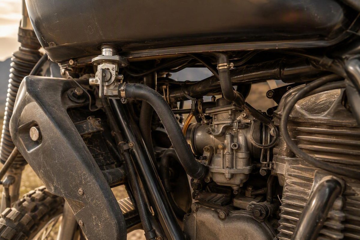
On supported carbureted KLR650s, the main hose joins the petcock outlet to the carburetor inlet. Fuel-injected and EVAP bikes need exact-model diagrams.
Quick Answer: Start at the Tank, Then Identify the Fuel System
On the carbureted KLR650 configurations covered by the available third-party evidence, the main fuel hose is the larger hose running from the tank petcock’s fuel outlet to the carburetor fuel inlet. The smaller hose beside it is the petcock vacuum hose, not a second fuel line. This larger-to-larger and smaller-to-smaller arrangement is described in a KLR650.NET owner discussion, but it is not a Kawasaki-verified routing instruction for every model year.
There is no single supported hose-routing description for every KLR650. Fuel systems, tank fittings, emissions equipment, vents, tees, and hose terminations vary by year, market, and installed equipment. Newer fuel-injected motorcycles must not be treated as though they have an older carburetor and vacuum-operated petcock.
Use this three-step decision process before disconnecting anything:
- Identify the motorcycle. Record the full model year, variant or model code, and market specification.
- Determine whether it is carbureted or fuel injected. Do not apply petcock-to-carburetor instructions to a fuel-injected model.
- Check for EVAP equipment. Look for an evaporative canister, additional tank pipes, vacuum tees, valves, or emissions hoses.
If the motorcycle is partly disassembled, do not identify a hose solely by color, age, or appearance. Replacement tubing may not match the original, and nearby hoses can look similar. Trace each line from one endpoint to the other.
For the conventional carbureted arrangement described by the cited sources:
- Larger petcock line ending at the carburetor fuel inlet: main fuel hose.
- Smaller petcock line ending at a vacuum source: petcock operating-vacuum hose.
- Line ending open, running downward, reaching the airbox, or connecting to emissions equipment: identify it from the applicable diagram before changing it.
This is a third-party-supported identification guide, not a manufacturer-verified, clip-by-clip routing procedure for every KLR650. If the motorcycle differs from the basic carbureted layout, documentation for its exact model and emissions configuration should control.
The Two Lines at a Carbureted KLR650 Petcock
A vacuum-operated petcock has two separate external connections. One carries fuel; the other supplies the vacuum signal used to operate the petcock.
| Line | Relative size | Starting point | Destination | Function |
|---|---|---|---|---|
| Main fuel hose | Larger | Petcock fuel outlet | Carburetor fuel inlet | Carries fuel from the tank to the carburetor |
| Petcock vacuum hose | Smaller | Petcock vacuum fitting | Carburetor- or intake-side vacuum source | Supplies the signal used to operate the petcock |
For the 1984–2007 KLR600/KLR650 models covered by a third-party repair manual, the large hose at the petcock is identified as the fuel line and the small hose as the vacuum line. The manual establishes the tank-end distinction; owner discussions supply the carburetor-end descriptions. Cyclepedia documents the large fuel line and small vacuum line at the petcock for those covered models.
Main fuel hose
Begin under the tank at the petcock. Locate the relatively larger fitting and trace the attached hose toward the carburetor. On an unmodified carbureted motorcycle matching the configurations discussed in the sources, it should end at the carburetor fuel inlet.
Use hose size only as an initial cue. A previous owner may have fitted non-original tubing, and age can alter a hose’s appearance. Confirm the endpoints rather than assuming that the thickest or darkest hose must carry fuel.
The installed route should not contain visible pinching, flattening, sharp bends, or unnecessary loops. Do not shorten or redirect it simply to create the shortest possible path; the correct clips, retainers, clearance, and hose length depend on the exact motorcycle.
Petcock vacuum hose
The smaller petcock fitting is associated with the operating-vacuum line. Trace that line to the specified vacuum source on the carburetor or intake side.
The vacuum signal permits a vacuum-operated petcock to pass fuel through its separate fuel outlet.
Do not mistake this smaller line for:
- A reserve-fuel hose.
- A carburetor vent.
- A tank vent or overflow-related line.
- An airbox drain.
- AIS or EVAP plumbing.
Some forum threads refer to numbered carburetor fittings shown in photographs. Those numbers should not be transferred to another motorcycle because the labels apply only to the pictured carburetor, and the referenced images are not fully represented in the available evidence. The useful distinction is functional: the main hose joins the petcock fuel outlet to the carburetor fuel inlet, while the vacuum hose joins the petcock to the applicable vacuum source.
How to Distinguish Fuel, Vacuum, Vent, Drain and Emissions Hoses
The most dependable identification questions are:
- Where does the hose begin?
- Where does it end?
Color is weak evidence.
| Hose or plumbing | Identification by endpoints | Function | Common confusion |
|---|---|---|---|
| Main fuel hose | Petcock fuel outlet to carburetor fuel inlet on the supported carbureted layouts | Supplies fuel to the carburetor | Mistaken for a vent or interchanged with the vacuum hose |
| Petcock vacuum hose | Smaller petcock fitting to a carburetor- or intake-side vacuum source | Operates the vacuum-controlled petcock | Mistaken for a second fuel or reserve hose |
| Carburetor vent | Carburetor vent fitting to its specified termination | Vents the applicable carburetor chamber | Mistaken for a disconnected fuel hose because one end may be open |
| Tank vent or overflow-related line | Tank fitting to the model-specified termination or EVAP component | Performs the function assigned by that tank and emissions configuration | Called a vent, overflow, or both in owner discussions |
| Airbox drain | Airbox drain point to a plugged hose or collection section | Collects material drained from the airbox | Mistaken for fuel plumbing when liquid is found near the rear suspension |
| AIS plumbing | Connects components in the air-injection system | Forms part of the emissions arrangement | Confused with vacuum or EVAP plumbing |
| EVAP plumbing | Connects the tank, canister, vacuum source, purge components, or other specified endpoints | Manages fuel vapor on equipped motorcycles | Mistaken for an ordinary tank vent or petcock vacuum line |
A standard carbureted configuration discussed by KLR owners was described as having a fuel hose, petcock vacuum hose, tank vent tube, and separate carburetor vent line. The same discussion identifies an evaporative canister and two pipes at the back of the tank as signs of an older California configuration. Those descriptions are owner guidance, not universal factory routing instructions.
Carburetor vent
In a forum discussion about a 1999 Generation 1 KLR650, contributors described the carburetor vent as a separate line routed downward and left open to the atmosphere. That is useful for distinguishing it from the fuel and petcock vacuum lines, but it applies to the motorcycle and carburetor under discussion rather than every KLR650. The 1999 carburetor discussion provides the model-specific endpoint descriptions.
Do not assume that every open-ended hose is disconnected. A vent may be intended to end open at a specified location. Conversely, do not leave an unknown hose open merely because it points downward. Trace it to its source and compare it with the correct diagram.
Tank vent or overflow-related line
The owner sources use “vent” and “overflow” inconsistently for downward-running tank lines. The available evidence does not support assigning one universal name, function, or termination point to every such hose.
The correct destination depends on the tank and emissions configuration. A standard arrangement may have a downward-routed line, while related plumbing on an EVAP-equipped motorcycle may connect to a canister or other emissions component. Do not shorten, plug, open, or reroute an unidentified tank line.
Airbox drain
In the forum-discussed 2008 KLR650, contributors identified a hose and small plugged collection bottle near the rear shock as the filtered-side airbox drain rather than the main fuel hose. That conclusion is specific to the motorcycle and context in the discussion and should be checked against the applicable manual before treating another hose the same way. The 2008 discussion distinguishes the airbox drain from the petcock vacuum and emissions lines.
AIS and EVAP plumbing
Their presence limits the usefulness of a simple two-line explanation.
Do not plug, omit, remove, or reroute an unidentified vent, AIS line, or EVAP hose. First establish the exact model and emissions configuration, then use the corresponding diagram. Previous modifications may mean the installed arrangement no longer matches either the standard or emissions-equipped factory layout.
Routing Differences by Year, Fuel System and EVAP Equipment
The available evidence supports three broad categories. They are identification boundaries, not interchangeable service procedures.
1984–2007 carbureted models covered by the third-party manual
For the 1984–2007 KLR600/KLR650 models covered by the cited Cyclepedia manual:
- The large petcock hose is the fuel line.
- The small petcock hose is the vacuum line.
Owner discussions add that the large hose leads to the carburetor fuel inlet and the smaller hose leads to the applicable vacuum source. The complete installed route—including clips, bends, retainers, and exact carburetor fitting placement—still requires documentation for the individual motorcycle.
Do not extend the manual’s date range because a later machine looks similar. A different model generation, emissions package, tank, petcock, or carburetor can change the layout.
Later carbureted examples represented by the 2008 discussion
The forum-discussed 2008 KLR650 supports a narrower conclusion: it had a petcock vacuum hose relevant to fuel flow, and one contributor reported that an overly long or heat-affected hose could kink and interfere with petcock operation.
That thread does not establish the main fuel hose’s complete route. It also reports that apparent hose pinching was corrected before the motorcycle returned to normal operation, but the sequence does not prove which hose or change resolved the problem.
California and other EVAP-equipped configurations
EVAP-equipped motorcycles have additional plumbing and should not be reduced to the standard fuel-and-vacuum pair.
In an older KLR owner discussion, an evaporative canister and two pipes at the rear of the tank are described as visual clues for a California configuration. A motorcycle’s present location does not establish its original specification because an emissions-equipped motorcycle may have moved to another region. The KLR Forum discussion explains the standard-versus-California distinction and the need for a separate diagram.
Contributors in the same thread describe a California Generation 2 arrangement with a vacuum tee connecting the carburetor vacuum source, petcock, and EVAP system. Treat that description as provisional owner guidance. It is not manufacturer-verified routing and should not replace the diagram for the exact year and market.
If the motorcycle has a tee, canister, purge connection, extra tank pipe, or disconnected emissions hose:
- Photograph the current layout.
- Identify both ends of each hose.
- Record any capped or altered connection.
- Consult the applicable vacuum and EVAP diagrams before changing the arrangement.
Newer fuel-injected motorcycles
Do not infer its fuel-line location from carbureted petcock instructions.
For the 2025 KLR650 Adventure ABS, model code KL650HSFNN, Kawasaki lists these official parts-diagram categories:
- Fuel Injection.
- Fuel Pump.
- Fuel Tank.
- Fuel Evaporative System—California.
The Kawasaki parts-diagram index for the 2025 KL650HSFNN confirms that these diagram categories are available. The index itself does not establish installed hose endpoints, clamp positions, access steps, or physical routing. Open the relevant full diagram and use the applicable service documentation.
Main and Reserve Use the Same External Fuel Outlet
On the carbureted petcock arrangement described by KLR owners, main and reserve do not use separate external fuel hoses.
The owner-forum explanation is:
- A taller internal pickup serves the normal main supply.
- A lower pickup provides access to the reserve supply.
- The petcock position selects the pickup.
- Both pickups discharge through the same external fuel outlet.
- The same main fuel hose carries fuel in both positions.
Accordingly, the second, smaller external petcock fitting should not be interpreted as the reserve outlet on these configurations. It is described as the vacuum connection. This pickup-height and shared-outlet explanation comes from owner-forum evidence rather than official Kawasaki documentation.
If the motorcycle has an aftermarket or replacement petcock, do not assume it operates like the original arrangement.
Safe Access and Inspection Before Disconnecting Anything
Start with a visual trace and remove components only when the intended work requires access.
For the 1984–2007 models covered by the third-party Cyclepedia procedure, turn the petcock to OFF before disconnecting the large fuel line or small vacuum line. The same procedure recommends protective gloves and eyewear. Its tank-removal sequence includes:
- Removing the side covers.
- Removing the seat.
- Disconnecting the battery negative lead.
- Disconnecting the fuel and vacuum lines after setting the petcock to OFF.
- Removing the rear tank bolts.
- Removing the radiator shrouds.
- Pulling the tank rearward and lifting it from the frame.
After installation, the procedure calls for checking that cables and wires are not pinched and confirming proper throttle operation. These are model-range-specific instructions, not a universal procedure for later KLR650s. Cyclepedia provides the documented removal and installation sequence.
Before disconnecting a hose:
- Confirm the motorcycle and applicable procedure.
- Photograph the existing connections, clips, and hose paths.
- Label similar hoses at both ends.
- Determine whether a clamp or retainer is fitted.
- Establish how any released fuel will be handled under the applicable service procedure.
Visual inspection checklist
Trace both endpoints of each suspected line and inspect for:
- Wetness, staining, or active leakage.
- Cracking, splitting, hardening, or swelling.
- Loose or disconnected ends.
- Flattening or collapse.
- Sharp bends and kinks.
- Pinching beneath the tank or bodywork.
- Contact with components that may damage the hose.
- Excessive length forming loops or deep low spots.
- A hose stretched tightly between fittings.
- Missing or displaced clamps.
- Routing that conflicts with the model documentation.
- Capped or altered emissions plumbing.
Do not use mouth-applied suction to test a vacuum petcock. That method appears in informal forum advice but is not presented in the evidence as a safety-validated procedure. When functional testing is required, follow the official service method and use suitable equipment.
After reconnecting the hoses, confirm that every connection is fully seated and retained as specified. Recheck the routing as removed components are installed, and complete the post-installation checks required by the applicable manual.
Troubleshooting Bogging or Fuel Starvation After Hose Work
Use a diagnosis-before-parts sequence. If bogging, stalling, or a no-start condition begins after tank or carburetor work, a disturbed hose is a reasonable inspection target, but timing alone does not identify the cause.
1. Verify line identity and endpoints
Confirm the following where applicable:
- Petcock fuel outlet to carburetor fuel inlet.
- Petcock vacuum fitting to the specified vacuum source.
- Carburetor vent to its documented route or termination.
- Tank vent and EVAP lines to their model-specific destinations.
- Airbox drain arranged as specified rather than connected to fuel plumbing.
Do not replace the petcock, fuel hose, or carburetor parts until the existing lines have been identified and checked for correct connection.
2. Inspect the main fuel-hose route
Trace the larger hose through its full path and look for:
- Pinching under the tank.
- A tight bend immediately after a fitting.
- A kink hidden behind bodywork.
- Excessive length.
- Deep low spots or unnecessary loops.
- Flattening against a bracket.
- An added filter or connector forcing an awkward angle.
A smooth, unobstructed route is a reasonable inspection target for the gravity-fed carbureted systems discussed in the owner evidence. Do not shorten or reroute the hose arbitrarily; retain the model-specified path, clearance, clips, and movement allowance.
3. Inspect the petcock vacuum hose
A clear main fuel hose cannot compensate for a vacuum-operated petcock that lacks the correct operating signal.
Inspect the smaller hose for:
- Disconnection at either end.
- Splitting near a fitting.
- Collapse or deterioration.
- Heat-related softening or kinking.
- Pinching beneath the tank.
- Excessive length forming a loop.
- Connection to the wrong carburetor fitting.
- Incorrect tee routing on an EVAP-equipped motorcycle.
A contributor to the 2008 discussion reported that an overly long vacuum line could kink when warm and interfere with fuel delivery. The same thread illustrates why improvement after moving hoses does not prove which line caused the fault.
4. Inspect tank venting without treating one clue as proof
Check the applicable tank vent path for visible pinching, blockage, disconnection, or routing that conflicts with the model documentation.
Forum contributors have suggested opening the fuel cap as a preliminary diagnostic clue when investigating bogging. That observation is not conclusive and does not identify the blocked component or establish a repair. This article does not recommend manipulating the cap while riding or improvising a running-engine test; use the applicable service procedure to investigate suspected venting problems.
5. Inspect an added inline filter
If an inline filter has been installed:
- Confirm its flow direction if it is directional.
- Determine whether the symptoms began after installation.
- Inspect both hose connections for kinks.
- Check whether its size or placement creates a deep loop.
- Look for visible contamination.
- Compare the installation with the applicable service information.
Owner discussions raise filter restriction as a possibility, but the supplied evidence does not establish that all aftermarket filters are restrictive or that one filter medium is universally preferable.
6. Inspect the carburetor vent separately
The carburetor vent is not the main fuel hose. Verify its source, route, and termination independently. A visibly pinched, blocked, plugged, or misidentified vent should be compared with the documentation for that carburetor and model.
For the forum-discussed 1999 Generation 1 motorcycle, owners described the vent as a separate downward-running atmospheric line. Do not transfer its pictured fitting labels or routing to another year without verification.
7. Escalate when the layout does not match
Stop trial-and-error troubleshooting and obtain the exact model documentation if:
- Either endpoint of a hose remains unidentified.
- Fuel is leaking.
- An EVAP canister, tee, or altered emissions line is present.
- A capped connection does not appear in the standard layout.
- The petcock, carburetor, or tank is not original.
- The motorcycle is fuel injected.
- Installed routing conflicts with the applicable diagram.
- The fault persists after the lines are identified and visibly unobstructed.
Moving hoses until the engine runs can hide an unresolved routing or connection problem. Record each change and verify the affected system rather than treating temporary improvement as proof.
How to Find the Correct Kawasaki Diagram for Your Motorcycle
Before selecting a diagram, record:
- Full model year.
- Exact KLR650 variant.
- Model code, if available.
- Market specification.
- Carbureted or fuel-injected system.
- Presence of an EVAP canister or extra tank fittings.
- Original or replacement petcock.
- Original or replacement tank and carburetor.
- Known fuel-system or emissions modifications.
Kawasaki owner and service documentation for the exact motorcycle should control when it conflicts with owner-forum guidance or a third-party manual covering a different range.
For the 2025 KLR650 Adventure ABS, model code KL650HSFNN, Kawasaki’s index lists:
| Official diagram category | Diagram ID |
|---|---|
| Fuel Injection | 340451 |
| Fuel Pump | 340450 |
| Fuel Tank | 340479 |
| Fuel Evaporative System—California | 340452 |
These identifiers confirm which diagram categories apply to that model. They do not, by themselves, prove an installed hose route or endpoint.
Owners of other years should select their own motorcycle rather than reusing the 2025 diagrams because both machines carry the KLR650 name.
In the complete parts diagram or service manual, confirm:
- Every hose’s starting and ending point.
- The function assigned to each fitting.
- Clip and retainer locations.
- Required clamps.
- Tank vent termination.
- Carburetor vent routing, where applicable.
- EVAP canister, valve, and tee connections.
- Fuel-pump and injection connections on fuel-injected models.
- Applicable part numbers.
- Access and disassembly requirements.
- Inspection and replacement procedures.
- Required post-installation checks.
Most detailed older-model connection descriptions in this article come from a third-party repair manual and owner forums. They are useful identification cues, but they are not substitutes for Kawasaki documentation covering the motorcycle’s exact model code and emissions specification.
Conclusion
For the carbureted configurations supported by the available evidence, trace the larger petcock hose to the carburetor fuel inlet and the smaller hose to the applicable vacuum source. Verify both endpoints rather than relying on hose color or appearance.
If the motorcycle is fuel injected, EVAP-equipped, modified, or does not match that arrangement, stop guessing. Identify the exact model and verify every connection against the applicable Kawasaki diagram or service documentation before disconnecting or rerouting a hose.
Frequently Asked Questions
Where does the main fuel hose connect on a carbureted KLR650?
On the carbureted arrangements described by the available third-party sources, the main fuel hose connects the petcock fuel outlet to the carburetor fuel inlet. It is generally the larger hose at the petcock. Trace the complete line to verify both endpoints rather than identifying it by size or color alone.
What is the smaller hose attached to the KLR650 petcock?
On the supported carbureted configurations, it is the petcock vacuum hose. It runs between the petcock’s vacuum fitting and a carburetor- or intake-side vacuum source.
Because that signal operates the vacuum-controlled petcock, a disconnected, collapsed, leaking, or kinked vacuum line may resemble a blocked fuel hose. EVAP-equipped motorcycles may have additional vacuum plumbing that requires a model-specific diagram.
Does the reserve position use a separate fuel hose?
Not on the carbureted petcock arrangement described in the owner evidence. Main and reserve use internal pickups at different heights, but both feed the same external fuel outlet and main hose. The smaller external connection is described as the petcock vacuum fitting, not a reserve-fuel outlet. The owner discussion explains the internal pickup heights and shared external outlet.
How can I tell whether my KLR650 has California EVAP plumbing?
For the older configurations discussed by owners, an evaporative canister and two pipes at the rear of the tank are clues to California EVAP equipment. Extra tees, vapor hoses, or emissions components may provide additional indications.
Do not identify the specification from the motorcycle’s current location. Confirm the model code, emissions label, tank connections, canister, and applicable Kawasaki diagram before changing the plumbing.
Which official diagrams apply to a 2025 KLR650 Adventure ABS?
For the 2025 KLR650 Adventure ABS, model code KL650HSFNN, Kawasaki lists:
- Fuel Injection: 340451
- Fuel Pump: 340450
- Fuel Tank: 340479
- California Fuel Evaporative System: 340452
These categories and identifiers appear in Kawasaki’s official 2025 KL650HSFNN parts-diagram index. Use the full diagrams and applicable service documentation to determine actual endpoints and routing; the index alone does not provide a verified installed hose path.