
Prove the Crank Signal Fault Before You Buy a Sensor
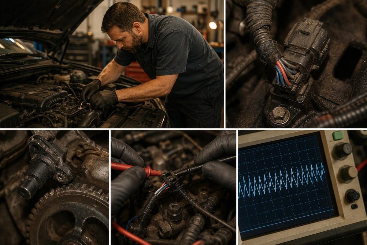
P0335 means the PCM lost a usable crank signal, not that the sensor died. Here is the freeze-frame, wiring and waveform sequence that finds the real fault.
There is no code “PO335.” What your scan tool is showing is P0335 — the letter P, the number zero, then 335 — which the diagnostic references define as “Crankshaft Position Sensor A Circuit Malfunction.” It means the powertrain control module (PCM) detected an unacceptable crankshaft-position signal or circuit condition. It does not prove the crank sensor is defective. The sensor, its connector, the harness, the reluctor wheel, the timing system and the PCM input all sit on that circuit, and the code cannot tell them apart. Record the code status and freeze-frame data before you touch anything, then follow the signal from the sensor to the PCM using the procedure for the exact vehicle.
Read the Code as P0335, Not PO335
Confirm the characters on the scan tool or the printed report: P, zero, 3, 3, 5. The cited diagnostic and manufacturer materials consistently identify P0335 as Crankshaft Position Sensor A Circuit Malfunction. Generic guidance starts with scan data, visible damage, wiring and connections, then waveform testing if needed — not automatic sensor replacement (AutoZone’s P0335 diagnostic overview).
Your first six moves:
- Do not clear the code yet.
- Record whether it is current, pending, stored or intermittent.
- Save the freeze-frame values and every related code.
- Note exactly when the symptom occurs.
- Inspect the sensor connector and the accessible harness.
- Pull the wiring diagram and diagnostic procedure for the exact year, make, model, engine and build.
Hard starting, a no-start, stalling or severe misfiring can make the vehicle unreliable. Whether it should be driven or recovered depends on how it behaves and on the manufacturer’s guidance; P0335 alone gives no universal drive-or-tow answer.
Pick how the engine behaves and which sensor design you have; the test path updates below.
P0335 test path picker
Engine runs: compare scan-tool RPM to the real engine
Watch live RPM while the engine runs and review related codes and data. Zero or implausible RPM with the engine running means test the CKP signal path from sensor to PCM. It does not mean replace the sensor.
No-start: evaluate CKP activity while cranking
Use the vehicle-specific procedure to check CKP activity or RPM during cranking, then compare against the manufacturer's expected result. There is no universal cranking-RPM threshold. A running-engine RPM check cannot diagnose a no-start.
Intermittent: hunt the dropout where the harness suffers
- Harness sections near heat sources or moving components
- Wiring that flexes with engine movement; rub points against brackets and covers
- Wiring stretched near recently removed parts
- Oil- or coolant-contaminated connectors; terminals that lose contact hot or when moved
- Broken or half-engaged connector locks
Monitor the signal under the reproducing condition when the approved procedure allows it. A dropout narrows the search; the circuit or component still has to be isolated.
Identify the sensor design before testing anything
Pull the wiring diagram for the exact year, make, model and engine. A passive variable-reluctance sensor and a powered Hall-effect sensor need different tests, and connector appearance alone is not a reliable way to tell them apart.
Variable-reluctance checks (manufacturer limits govern)
- Sensor resistance against the spec for this application
- Unintended path to ground
- Generated AC voltage while cranking or running
- Signal waveform for missing or irregular pulses
- Mounting, specified air gap, contamination, reluctor condition
Do not apply a Hall-effect supply-voltage test here. A resistance value from a different engine does not pass or fail this sensor.
Hall-effect checks: power and ground before signal
- Specified power-supply circuit present at the connector
- Sensor ground
- Signal circuit and expected switching behavior
- Approved probing points and test conditions
- Then mounting and reluctor condition
Do not use a passive sensor's resistance test as the deciding test on a powered sensor.
Sensor replaced, code back: recheck in this order
- Confirm the part matches the exact application and connector
- Verify seating, clean mounting face, orientation, specified air gap
- Inspect the mounting area and tip for contamination
- Check connector pin fit and terminal tension
- Test the harness under the failure conditions
- Verify specified power and ground on powered designs
- Measure the signal at the sensor
- Confirm the signal reaches the PCM
- Inspect reluctor and timing system
- Consider the PCM only after all of the above pass
Optional: Scion tC/xB 2AZ-FE freeze-frame check (Toyota S-SB-0025-12)
Sources: AutoZone P0335 overview; APEX Tech Nation sensor-design overview; Toyota bulletin S-SB-0025-12 (Oct 15, 2012, NHTSA archive). The ~185°F threshold is the bulletin's approximate figure; whether the 2012 bulletin is still current is not established here.
What the PCM Watches and Where the Circuit Can Fail
The crankshaft-position (CKP) sensor reads a reluctor or trigger wheel. As the crankshaft turns, the sensor produces a changing signal that lets the PCM determine crank position and engine speed. Depending on the vehicle, the PCM uses that for starting, ignition, injection and misfire monitoring.
Symptoms range from a check-engine light with no drivability complaint to extended cranking, a no-start, intermittent stalling, rough running, misfires, hesitation and a dead or erratic tachometer. None of those is a component test. A no-start cannot distinguish between the sensor, the connector, the harness, the trigger wheel, the timing system and the PCM input.
Fault areas on the circuit:
- Sensor: internal failure, contamination or physical damage
- Connector: loose engagement, corrosion, damaged or loose-tension terminals
- Wiring: opens, shorts to ground or voltage, wires shorted together, rubbed insulation, intermittent conductors
- Supply circuits: wrong power or ground on designs that need them
- Installation: poor seating, debris at the mounting face, wrong air gap
- Trigger system: damaged reluctor or signal teeth
- Mechanical timing: timing-system damage or a crankshaft keyway problem
- Module side: damaged terminals, poor connections or a PCM input fault
There is no supported failure-rate evidence here for ranking those causes. Let the service history, code status, measurements and failure conditions set the test order.
Scan-tool RPM is one useful clue. If the engine is physically running but the scan tool shows zero or an implausible RPM, the CKP signal path is where to look. That observation still does not say which part of the path failed.
Save the Freeze-Frame Data Before You Clear Anything
Freeze-frame data records the operating conditions the PCM saw when it set the code. It is gone the moment you clear codes, and it is the only thing that can match a vehicle to a bounded bulletin like the Scion example below.
Before disconnecting the sensor, moving the harness or clearing codes, write down: year, make, model; engine and transmission; VIN or build information; the exact code display and status; related DTCs; symptoms; coolant temperature and RPM; vehicle speed and load; battery or system voltage; any other freeze-frame values; and recent engine, transmission, wiring or timing work.
Also record whether the problem shows up during cranking, immediately after start, at idle, only when hot, over bumps, during acceleration, when the engine or harness moves, or after work in the area. These are inspection leads, not proof. A fault that first appeared after transmission work makes disturbed connectors and harness routing the logical first look, but it does not establish the cause.
Do not apply a resistance value, pinout, voltage threshold, air-gap spec, cranking-RPM threshold or waveform limit from a generic source. Every one of those must come from the procedure for the exact application.
Match the Test Path to How the Engine Behaves
| Condition | First test direction | What it tells you |
|---|---|---|
| Engine runs | Compare scan-tool RPM with what the engine is actually doing; review related data and codes. | Missing or implausible RPM calls for CKP signal-path testing, not a sensor. |
| No-start or long crank | Use vehicle-specific service information to evaluate CKP activity or RPM during cranking. | Compare against the manufacturer’s procedure; there is no universal cranking-RPM threshold. |
| Intermittent stall or code | Inspect connectors and harness sections exposed to heat, movement, rubbing, vibration or recent service; monitor the signal under reproducible conditions. | A dropout narrows the search, but the circuit or component still has to be isolated. |
A running-engine RPM check cannot diagnose a vehicle that will not start. A no-start may require scan data or direct signal measurement while cranking, but the expected result and the test setup must come from the correct service information.
For an intermittent fault, inspect harness sections near heat sources and moving components, wiring that flexes with engine rock, rub points against brackets and covers, wiring stretched near recently removed parts, oil- or coolant-contaminated connectors, terminals that lose contact when hot or moved, and broken or half-engaged connector locks.
Use the manufacturer’s approved cranking or running test setup, proper back-probing methods and correctly rated equipment. Check every related DTC before choosing a branch.
Test a Variable-Reluctance Sensor Differently From a Hall-Effect Sensor
Start with a visual and physical inspection: sensor seating, debris at the mounting face, connector engagement, terminal condition, corrosion, rubbed insulation, stretched wires, routing and damage near recently serviced components.
Then identify the sensor design from the correct wiring diagram. Connector appearance alone is not enough when manufacturer information is available.
A Variable-Reluctance Sensor Generates Its Own AC Signal
A variable-reluctance CKP sensor is passive. It generates an AC signal as the reluctor teeth pass the sensor tip. The application-specific procedure may call for checks of sensor resistance, an unintended path to ground, generated AC voltage while cranking or running, signal waveform, mounting and specified air gap, and reluctor condition.
The manufacturer’s limits govern. A resistance value taken from another engine — even one from the same manufacturer — does not tell you whether this sensor passes.
A Hall-Effect Sensor Needs Power and Ground First
A Hall-effect CKP sensor requires power and ground and produces a switching signal. Use the wiring diagram and procedure to identify the specified supply circuit, the sensor ground, the signal circuit, the expected switching behavior, and the approved probing points and test conditions.
Do not apply a Hall-effect supply-voltage test to a passive variable-reluctance sensor, and do not use a passive sensor’s resistance test as the deciding test on a powered Hall-effect sensor. These design distinctions are described in the cited technical overview, but the vehicle’s wiring diagram and procedure remain controlling (APEX Tech Nation’s sensor-design overview).
Static tests have limits. Resistance or unloaded continuity can read fine when the fault only appears with heat, movement, poor terminal contact or dynamic operation. In one unresolved DF Kit Car forum case, a member reported in-range resistance and low circuit resistance, yet P0335 remained after sensor replacement. With no confirmed final repair, the case shows only that the reported static checks and the replacement did not isolate the fault (DF Kit Car forum diagnostic sequence).
When inspection and basic circuit checks are inconclusive, the correct waveform procedure can show missing or irregular pulses a meter cannot. Interpret the pattern only against application-specific information.
| Test result | Next area to investigate |
|---|---|
| No signal from a passive sensor | Application-specific generated-signal test, seating, specified air gap, contamination, reluctor condition, mechanical timing |
| No switching signal from a powered sensor | Specified power supply, ground, connector terminals, signal circuit, then mounting and reluctor condition |
| Signal at sensor but not at PCM | Connector pin fit, opens, shorts, harness routing, PCM-terminal condition |
| Irregular pattern, or valid signal at PCM | Reluctor condition, mounting, air gap, timing integrity, related cam/crank codes, module power and grounds, OEM diagnostic logic |
Leave PCM diagnosis until sensor output, terminal condition, wiring integrity, applicable power and grounds, and signal arrival at the module have all been verified under the conditions that trigger the fault.
When a New Crank Sensor Did Not Clear P0335
A 2004 Suzuki Jimny owner reported that P0335 and extended cranking continued after replacing both the crankshaft and camshaft sensors. The thread never documented a confirmed final repair, so it proves no cause; it shows why installing a sensor is not a diagnostic result (BigJimny owner report).
Recheck in this order:
- Confirm the replacement part — exact application, connector and physical configuration.
- Verify installation — full seating, clean mounting face, correct orientation, specified air gap where applicable.
- Inspect for contamination at the mounting area and sensor tip as the manufacturer directs.
- Check connector pin fit for backed-out, damaged, corroded or loose-tension terminals.
- Test the harness under the failure conditions — opens, shorts, rubbing, heat damage, movement faults.
- Verify specified power and ground on powered designs.
- Measure the signal at the sensor with the correct procedure.
- Confirm the signal reaches the PCM.
- Inspect the reluctor and timing system per manufacturer instructions.
- Consider the PCM only after its inputs, connections, power and grounds pass.
Do not install another sensor, or jump to a PCM, because the first part did not fix the code. Installation, air gap, contamination, damaged signal teeth, timing faults, terminal condition or an intermittent harness can all still be untested.
Scion 2AZ-FE Bulletin: P0335 Fixed by a Timing Gear, Not a Sensor
Toyota bulletin S-SB-0025-12, dated October 15, 2012, shows why vehicle identity and freeze-frame data matter. Its stated application is the 2005–2010 Scion tC and 2008–2012 Scion xB equipped with the 2AZ-FE engine.
The bulletin addresses an intermittent malfunction indicator lamp with P0335 stored. Its qualifying freeze-frame conditions are coolant temperature of approximately 185°F (85°C) or higher and engine speed below 1,000 RPM. When the model, engine and freeze-frame conditions all match, the bulletin directs replacement of the camshaft timing gear assembly. If they do not match, it says to use the applicable repair-manual diagnosis (Toyota bulletin S-SB-0025-12 archived by NHTSA).
Treat this as a tightly bounded historical example, not a universal repair. The supplied evidence does not establish whether the 2012 bulletin has been superseded. It does not apply to other models or engines, nor to every P0335 on the listed Scions, and its repair is timing-system work rather than a sensor procedure. The warranty terms it records applied when it was issued; they do not verify present coverage for a particular VIN. Check current manufacturer service information against the vehicle’s VIN before relying on it.
Confirm the Repair Under the Original Failure Conditions
Clear P0335 only after the original code status, related DTCs and freeze-frame data are saved. Then verify the repair under the conditions that produced the failure, following the manufacturer’s procedure:
- Restart the engine or perform the specified cranking check.
- Test-drive the vehicle when appropriate.
- Reproduce the original hot, idle, acceleration, vibration or restart condition where practical.
- Rescan for current and pending codes.
- Confirm the original starting, stalling, misfire or intermittent symptom has not returned.
- Review live RPM or CKP data for plausible, stable operation.
- Check whether the exact vehicle and repair require a crankshaft-position variation relearn.
A relearn is not universal. If P0335 returns, continue from the measured findings rather than replacing another part without evidence.
The test-before-parts rule is short: verify the code is P0335, preserve the scan evidence, identify the sensor design and the exact vehicle procedure, and follow the signal from the sensor to the PCM. Repair only the component or circuit that fails the applicable test, then reproduce the original conditions and rescan.