
Test a CHT Sensor Before Replacing It
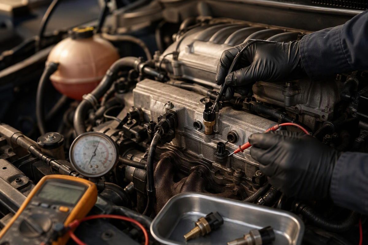
Test a cylinder head temperature sensor with cold-soak comparisons, scan data and circuit checks while separating sensor faults from real overheating.
Test a cylinder head temperature (CHT) sensor before replacing it. A trouble code or over-temperature warning does not prove the sensor is bad: the cause may be an open or shorted circuit, an inaccurate sensor, or genuine overheating that the sensor correctly detected.
Choose the observed code and temperature behavior to identify the next test.
CHT Diagnostic Starting Point
Match the scan result to the engine's behavior. The result identifies the first diagnostic path, not a replacement verdict.
Source basis: Ford OBD documentation cited in the article. Ford thresholds and monitor behavior are not universal specifications.
A CHT Sensor Measures Cylinder-Head Metal
A CHT sensor measures the temperature of the cylinder-head metal. It is not necessarily an engine coolant temperature (ECT) sensor under another name.
That distinction matters when coolant is low or air is trapped in the system. Coolant temperature may no longer represent the hottest part of the engine, while a CHT sensor in the head can continue reporting metal temperature. Ford describes this distinction directly and, on the systems documented, calculates temperature values used by the powertrain control module and onboard diagnostics from the CHT input (Ford 2010 OBD system summary, pp. 100–103).
Automotive analog temperature sensors commonly use a negative-temperature-coefficient element: resistance falls as temperature rises. The control module interprets the resulting signal as temperature. Bosch identifies cold-start, warm-operation and fan control among the uses for this type of temperature input (Bosch temperature-sensor overview).
The exact circuit, calibration and sensor location vary by engine. A vehicle may use CHT, ECT or multiple temperature inputs. Confirm the VIN, model year and engine before selecting a wiring diagram, connector pinout or test value.
Symptoms Point to Tests, Not Automatic Replacement
A CHT sensor or circuit fault may produce:
- a check-engine light and stored temperature-sensor circuit code;
- an implausibly cold or hot scan-tool reading;
- a reading that jumps when the harness is moved;
- unexpected cooling-fan operation;
- altered cold-start, fueling or engine-protection behavior; or
- reduced power or fail-safe cooling on applications that support it.
These symptoms are not proof of a failed sensor. Low coolant, trapped air, wiring damage, poor terminal contact, a cooling-fan fault, a thermostat problem or actual overheating can produce overlapping results.
On the Ford systems covered by its 2024–2025 OBD documentation, CHT-related definitions include P1289/P1289-00 and P017D/P017A-17 for high input, P1290/P1290-00 and P017C/P017A-16 for low input, and P1299/P1299-00 for fail-safe cooling. Ford lists typical circuit-fault thresholds below 0.244 V or above 4.96 V and identifies P1299 as an over-temperature/fail-safe event—not a declaration that the sensor failed (Ford 2024–2025 OBD summary, pp. 108–114). Those voltages are Ford monitor thresholds, not universal specifications.
Record Codes Before Clearing Them
Read stored, pending and manufacturer-specific codes before clearing anything. Save freeze-frame data, including CHT, ECT if equipped, intake-air temperature, engine speed, vehicle speed and calculated load.
A circuit-high or circuit-low code directs the first checks toward the connector and wiring. An over-temperature code set under heavy load requires cooling-system diagnosis as well as validation of the sensor reading.
Compare Cold-Soak Temperatures
Leave the vehicle off long enough for the engine to approach ambient temperature; overnight is useful. Before starting it, compare CHT with intake-air temperature, ambient temperature and ECT if available.
The readings should be reasonably close unless a block heater, direct sun or recent operation has warmed one sensor differently. As one reference—not a universal pass/fail rule—Ford documented a six-hour soak and a 30°F correlation tolerance in an IAT-versus-CHT/ECT monitor strategy (Ford 2007 OBD system summary, pp. 99–101). Use service information for the exact vehicle when it provides a specific limit.
Stop and investigate if CHT shows an extreme value or differs sharply from the other cold sensors. On a conventional pull-up circuit, an extreme-cold reading often accompanies an open or high-voltage condition, while an extreme-hot reading can accompany a short or low-voltage condition. Confirm that logic against the correct wiring diagram rather than replacing the sensor from the PID alone.
Graph the Warm-Up Curve
Start the cold engine and graph CHT. The reading should rise progressively rather than remain fixed, drop out or jump abruptly. Wiggle-test the accessible harness and connector while watching the graph.
A jump that follows harness movement points toward wiring, terminal contact or a connector problem. A fixed or implausible reading also requires circuit testing before condemning the sensor.
If temperature climbs smoothly into an unsafe range, treat it as possible real overheating. Check coolant level only when the engine is cold, then follow a complete cooling-system diagnostic sequence. Never open a hot, pressurized cooling system.
Inspect the Circuit Before Testing Resistance
With the ignition off, inspect for:
- spread, corroded or contaminated terminals;
- wiring rubbed through near the head, intake or brackets;
- heat-damaged insulation;
- poor terminal tension; and
- previous splices.
Next follow the OEM wiring diagram and pinpoint test. Depending on the design, this may include checking the PCM bias signal, sensor return, shorts to power or ground, and end-to-end wire resistance. Do not assume every two-pin temperature sensor uses the same pinout.
Ford’s documented CHT circuit illustrates why a generic voltage chart is risky. Its cold-range table places approximately 4.9 V at the extreme-cold end, but the circuit switches transfer functions for higher temperatures. Test the signal under the conditions and at the pins specified for the exact engine.
Use the Vehicle-Specific Resistance Chart
Measure resistance only when the service procedure supports that test. With the ignition off and the sensor disconnected, compare measured resistance at a known sensor temperature with the manufacturer’s temperature/resistance table. Never measure resistance on a powered circuit. A single reading without a known temperature proves little.
Replace the sensor when it is open, shorted, outside the applicable chart or repeatably drops out during a controlled temperature or harness test—and only after its wiring and terminals pass. If scan data is wrong while the sensor checks correctly, continue testing the circuit and PCM connections.
An Over-Temperature Code May Identify a Cooling Fault
A valid hot reading can expose a mechanical cooling fault. Ford’s 2026 service message for certain 2023–2025 Escape 1.5L EcoBoost vehicles built on or before September 16, 2024, associates P1285 and/or P1299 during hard acceleration or high load with machining chips restricting a coolant passage near the CHT2 port.
Ford directs a defined reproduction test, cooling-system flush and reevaluation, followed by cylinder-head replacement if the concern persists—not automatic CHT sensor replacement (Ford SSM 55142). That instruction applies to the specified vehicles and conditions, not to every engine with those codes.
If overheating is accompanied by recurring coolant loss, persistent exhaust vapor, cooling-system bubbles or contaminated oil, continue with tests that separate a head-gasket leak from a cracked head.
Verify the Repair Under the Original Conditions
CHT location and access are engine-specific. A sensor may sit in a dry bore rather than a coolant passage, so coolant-draining requirements vary. Before removal, check the service procedure for intake-component removal, seals, thread preparation, tightening torque and any required PCM reset or verification.
After repair, clear codes only after recording them. Repeat the cold comparison and warm-up graph, then reproduce the original operating conditions when it is safe to do so. A stable, plausible CHT reading with no returning circuit or over-temperature code is stronger confirmation than a successful parts swap alone.