
Recognize Camshaft Sensor Symptoms and Confirm the Actual Fault
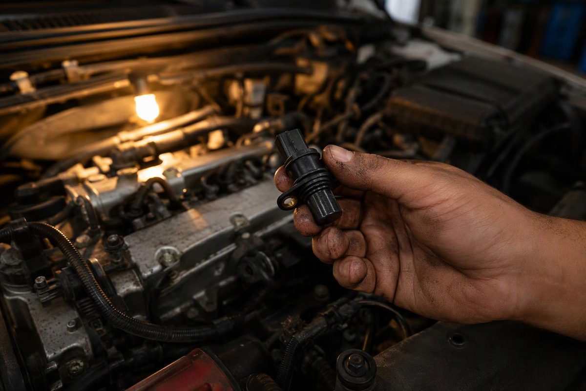
Learn which starting and running problems suggest a camshaft signal fault, what P0340 means, and which wiring and waveform tests justify sensor replacement.
Camshaft position sensor symptoms include extended cranking, crank-but-no-start, stalling, rough running, reduced-power operation and a check engine light—but none proves the sensor has failed. Damaged wiring, incorrect sensor clearance or a damaged trigger wheel can produce similar symptoms. Pico Technology’s diagnostic guide identifies these symptoms and alternative causes. Confirm whether the engine computer receives a usable camshaft signal when the fault occurs before buying a sensor.
Select the evidence you have; the tool identifies the next diagnostic step.
Camshaft Signal: Next Test
Next Diagnostic Step
Symptoms or P0340 only: gather evidence.
Save codes and freeze-frame data, identify the exact sensor, then inspect its connector, wiring and mounting. A symptom match or circuit code does not justify replacement.
Supply or ground fails: diagnose the circuit.
Check the feed, ground, connectors and any shared circuit against OEM specifications. Do not replace the sensor to correct a failed supply or ground.
No usable signal: check mounting and trigger condition.
With the engine turning and required circuits verified, investigate the sensor, mounting clearance and trigger wheel. Missing output alone does not isolate the sensor electronics.
Signal changes between sensor and computer: check the harness.
Confirm both measurements under the same conditions. Inspect intervening wiring and terminals before evaluating the computer’s input circuit.
Clean signals with incorrect correlation: investigate timing.
Use a matching engine reference and operating conditions. Check mechanical timing, trigger alignment and valve-timing control; correlation codes alone do not identify the failed part.
Sensor isolated by tests: replacement is justified.
This requires passing supply and ground tests, acceptable mounting and trigger condition, and output that fails the vehicle-specific test. After repair, repeat the original failing condition and follow any required OEM relearn.
Sources: Pico Technology CMP guided test, HELLA CMP troubleshooting, Subaru 11-130-13 and GM 12-06-01-009F; see article references. Use vehicle-specific specifications.
What Camshaft Sensor Symptoms Can Tell You
The camshaft position sensor, often abbreviated CMP, identifies camshaft reference positions. The engine computer uses that information for injection timing, ignition control on gasoline engines and variable valve timing, depending on the design. Pico’s guide explains these functions.
| Symptom | What To Record |
|---|---|
| Long cranking or no start | Cold start, hot restart or every start |
| Unexpected stalling | Idle or driving; immediate restart or not |
| Rough idle, misfires or hesitation | Operating conditions when it happens |
| Warning light or reduced power | Codes and whether operation changes |
A missing or unreliable cam signal can interfere with starting, but the effect varies by engine and sensor position. Intermittent signal loss is one possible cause of stalling—not a diagnosis. Rough running also requires consideration of ignition, fueling and mechanical problems.
The computer may detect a cam-position fault and enter a fallback strategy, so the vehicle can still run despite the fault. HELLA lists starting difficulties, stored codes and emergency-program operation.
An OEM example shows why sensor location matters: Subaru bulletin 11-130-13 documents rough idle, extended cranking and no start from incorrect sensor clearance on specified FA/FB applications. It explicitly says incorrect exhaust cam-sensor clearance does not cause a starting problem on those applications. That distinction should not be generalized to other engines.
Repeated Stalling or Severe Misfiring Calls for a Safe Stop
Repeated stalling, severe misfiring or major power loss calls for a safe stop and a tow rather than a diagnostic road test. A steady check engine light with normal operation still needs prompt diagnosis, but does not identify a failed sensor. If the light flashes, follow the separate guidance for a flashing check engine light.
Diagnose the Camshaft Signal Before Buying a Sensor
Save Codes and Identify the Exact Circuit
Before clearing anything, record the vehicle year, model and engine code, along with any recent timing or engine work. Save stored and pending codes and available freeze-frame data. Note whether the fault occurs during cranking, warm idle, acceleration or a hot restart.
P0340 identifies a camshaft position sensor “A” circuit malfunction; it is not a replacement instruction. Wiring, connectors, the reluctor wheel and internal timing components can also be involved. Kelley Blue Book’s P0340 reference explains these alternatives.
Use the vehicle’s service information to locate the specified bank and sensor. Do not assume “A” means the easiest sensor to reach or that another engine’s connector pinout applies.
If crankshaft codes are also present, include the crankshaft-signal diagnostic sequence rather than treating every starting problem as a CMP fault.
Inspect the Connector, Harness and Mounting
With the engine off, inspect for a loose connector, corrosion, damaged terminals, chafed wiring and a cracked sensor housing. Check whether the sensor is fully seated and whether recent repairs disturbed its mounting or wiring.
Repair an identified connection fault before condemning the sensor. HELLA’s troubleshooting procedure specifically recommends inspecting electrical connections for breaks and corrosion, and checking sensor-to-trigger-wheel distance and seal fit.
Verify Supply and Ground Against the Wiring Diagram
Identify the sensor type and terminal functions first. There is no universal CMP resistance or voltage specification suitable for every vehicle.
For the Hall-effect example in HELLA’s guide, the ignition-on supply is approximately 5 V, with an explicit instruction to follow manufacturer specifications. That is an example—not permission to apply 5 V to an unknown terminal.
Use suitable back-probes or breakout leads without spreading terminals. Check supply and ground under the conditions specified by the OEM. Perform resistance checks only on de-energized circuits, with components disconnected as the procedure requires.
If supply or ground fails its specified test, diagnose that circuit first. A new sensor cannot correct a missing feed or defective ground.
Capture the Signal During the Fault
An oscilloscope is more useful than a single averaged voltage reading for finding missing pulses or intermittent dropouts. A Hall-effect sensor should produce a switching waveform. Pico’s example switches between approximately 0 and 5 V, but actual voltage levels and pulse patterns must match the engine’s specifications. Its guided test also cautions that vehicles require different settings.
Compare the cam and crank signals with the OEM pattern or a verified reference from the same engine, under matching operating and valve-timing conditions. Subaru’s bulletin specifically calls for capturing both to identify cam-signal inconsistencies.
| Test Result | Next Diagnostic Direction |
|---|---|
| Supply or ground is incorrect | Feed, ground, connector or shared circuit |
| No usable signal at the sensor while the engine turns, despite verified circuits | Sensor, mounting gap or trigger wheel |
| Signal is correct at the sensor but faulty at the computer under the same conditions | Intervening harness and terminals, then computer input circuit |
| Both signals are clean but their relationship differs from the correct reference | Mechanical timing, trigger alignment or valve-timing control |
These results direct the next test; they do not identify a replacement part by themselves.
If the problem happens only hot, a good cold waveform does not settle the diagnosis. Repeat the capture during the failing restart or operating condition. Keep leads clear of belts, fans and hot exhaust components; leave inaccessible running-engine tests to a technician.
Separate Sensor Failure From Clearance and Timing Faults
A bad waveform does not automatically mean bad sensor electronics. Subaru’s April 2013 bulletin includes the 2013 Legacy and Outback 2.5L and specifies 1.25–1.35 mm clearance in its intake cam-sensor measurement procedure. That is a platform-specific specification, not a universal gap or a reason to add washers to another engine.
Correlation codes deserve a timing diagnosis. GM bulletin 12-06-01-009F documents stretched timing chains setting P0016–P0019 on listed 2007–2012 High Feature V6 applications. Those codes alone do not justify either a sensor or a timing-chain replacement.
Replace the Sensor Only When Tests Isolate It
Replace the sensor when vehicle-specific tests isolate it: its required circuits pass, mounting and trigger condition are acceptable, and its output fails the specified test. Repair wiring, mounting or timing faults when the evidence points there instead.
After repair, repeat the original failing condition and check for returning codes and signal faults. Follow any OEM-specified initialization or relearn procedure; do not assume every CMP replacement needs one. A cleared warning light alone is not proof that the fault is fixed.