
Low Fuel Pressure Does Not Automatically Mean a Bad Pump
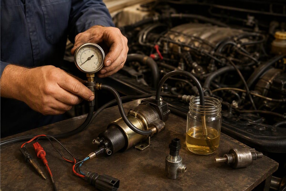
Diagnose low fuel pressure by comparing specified, commanded and measured pressure, then testing flow, voltage drop, restrictions and control inputs.
Low fuel pressure can cause extended cranking, a no-start, hesitation, lean operation, misfires or loss of power under load. It does not prove that the fuel pump has failed.
A restricted filter or pickup, a poor electrical connection, a faulty pressure sensor, regulator leakage, contaminated fuel or inadequate supply to a high-pressure pump can produce a similar result. The useful question is:
Is measured pressure below the specification for this exact engine under the condition where the symptom occurs—and, if so, why?
First identify which pressure is low
Do not connect a generic gauge until you know the fuel-system design.
- Port-injected gasoline engine: A suitable gauge may connect to a low-pressure rail service port, if one is provided.
- Gasoline direct-injection engine: It has a low-pressure supply side and an engine-driven high-pressure side. Scan data may report both.
- Common-rail diesel: Low-side supply pressure and high-pressure rail pressure are separate measurements. A P0087 “fuel rail/system pressure too low” code does not identify the in-tank or lift pump by itself.
- Electronic returnless system: A control module may vary pump output in response to requested pressure and sensor feedback. For example, GM describes one system in which the ECM sends desired pressure to a fuel-pump driver module and uses a feed-line pressure sensor for closed-loop control (GM service bulletin 19-NA-091).
Use service information for the VIN, engine and model year to find the correct test point, pressure range and test conditions. A Schrader-valve tester is not universal: Bosch restricts one common kit to compatible gasoline fuel-rail test ports and excludes diesel and flex-fuel applications (Bosch Diagnostics).
Never loosen a high-pressure gasoline or diesel line to check for fuel. High-pressure diesel can penetrate skin; a Stellantis service procedure warns that pressure can reach 2,000 bar/29,008 psi (NHTSA-hosted Stellantis procedure). Intrusive high-pressure testing requires the specified equipment, procedure and training.
Save the data before disturbing the fault
Scan the applicable modules and record:
- Stored, pending and history codes
- Freeze-frame engine speed, load and fuel pressure
- Desired and actual low-side pressure, if supported
- Desired and actual rail pressure on a GDI or common-rail diesel
- Fuel-pump command, duty cycle or speed
- System voltage
- Fuel trims and misfire counts on gasoline engines
Reproduce the complaint safely while logging data. A pressure value that meets specification at idle but falls during acceleration is more useful than one key-on reading.
For a no-start, record pressure while cranking—not only with the key on. Also confirm adequate cranking speed and check whether the engine controller is commanding fuel delivery.
Test pressure under the conditions that matter
Follow the OEM pressure-relief and gauge-connection procedure. Keep ignition sources away, use an approved fuel container and check every test connection for leakage before starting the engine.
- Key on, engine off: Does the system prime and reach its specified pressure within the allowed time?
- Idle or cranking: Does pressure remain within specification for that condition?
- During the complaint: Does pressure stay in range as fuel demand rises?
Where the design and service procedure permit, compare an external gauge with the scan-tool pressure PID:
- Gauge and PID both show low pressure: Continue with hydraulic supply, electrical power and pump-control tests.
- Gauge is in specification but the PID reads low: Test the pressure sensor, reference voltage, ground and signal circuit before replacing the pump.
- PID appears correct but the gauge reads low: Recheck the gauge, adapter, test point and specification.
A brief prime sound does not prove adequate pressure or flow. Normal pressure at idle also does not prove that the pump can meet demand under load.
Use pump command to choose the next test
On a variable-output system, view actual pressure beside requested pressure and pump command:
| Result when pressure falls | Diagnostic direction |
|---|---|
| Pump command rises toward its expected upper range | Check loaded supply voltage, ground, connector condition, filter or pickup restriction, fuel level and pump output |
| Pump command stays unexpectedly low | Check requested pressure, pressure-sensor plausibility, controller inputs, related codes and applicable service information |
| Mechanical pressure is correct but reported pressure is wrong | Test the pressure-sensor circuit |
| Low-side pressure is correct but rail pressure is low | Continue with the engine-driven pump, metering or regulating hardware and injector-leakage tests specified for that engine |
That final split prevents replacement of the wrong pump. Volkswagen’s procedure for specific 2009–2012 2.0L common-rail TDI models requires low-side supply-pressure testing and injector and pressure-regulator leakage checks before the high-pressure pump is condemned (Volkswagen technical bulletin).
Test the electrical circuit under load
An unloaded continuity check—or simply finding battery voltage at a disconnected plug—can miss resistance that appears while the pump draws current. Test with the connector attached and the pump operating or commanded on. Use proper back-probes so the terminals are not spread.
Measure voltage drop on both sides of the circuit:
- Battery positive to the pump power terminal
- Pump ground terminal to battery negative
Delphi’s general electric-pump procedure calls for less than 0.2 V on the power side and less than 0.2 V on the ground side. Those are useful screening values, not universal specifications; use the vehicle manufacturer’s limits when available. Delphi also warns that a poor ground can mimic more serious pump faults and says not to force meter probes into harness terminals (Delphi).
If the drop is excessive, test smaller sections of the circuit to locate resistance in a fuse connection, relay, wire, connector, module output or ground. Repair heat-damaged or loose terminals rather than installing another pump on the same faulty circuit.
If power, ground and command are correct, compare pump current with vehicle-specific information when available. Current draw or a current waveform can support the diagnosis, but it does not replace a pressure or delivery test.
If pressure falls only as demand rises
Pressure that is acceptable at idle but falls under load points toward inadequate delivery. Check in a vehicle-specific order:
- Fuel level, including whether the fault changes on turns, grades or with a nearly empty tank
- A restricted external filter, in-tank strainer or damaged line
- Tank venting, if the OEM procedure includes that test
- Aerated fuel or an air leak on the suction side of a diesel system
- Pump voltage and ground while the failure is occurring
- Specified delivery volume or low-side supply pressure
- Fuel quality and contamination
Do not clamp a return line or deadhead a pump unless the manufacturer’s procedure explicitly requires it. An incorrect restriction can damage components or create unsafe pressure.
Do not assume every low-pressure result means a clogged filter. The filter should be serviced according to the vehicle’s schedule and confirmed test results; see how to determine the correct fuel-filter interval.
On the GM diesel applications covered by bulletin 18-NA-361, water, debris or diesel-exhaust-fluid contamination can cause driveability complaints and component damage. GM directs technicians to inspect the filter and separator reservoir and, for the conditions covered, flush the system before continuing diagnosis rather than automatically replacing the entire fuel system (GM bulletin 18-NA-361). Other engines require their own contamination procedure.
Pressure decay does not identify the pump
If pressure reaches specification but falls too quickly after shutdown, possible leak paths include:
- Pump check valve
- Injector leakage
- Pressure-regulator leakage
- An external fuel leak
- An internal leak in a high-pressure circuit
Inspect first for external leakage, then follow the manufacturer’s isolation or leak-down procedure. Do not replace the pump solely because residual pressure falls. If the system has a serviceable regulator, use the applicable fuel-pressure regulator tests before naming the failed part.
Evidence that supports pump replacement
Pump replacement is supported when the relevant checks agree:
- Pressure or delivery volume is below the exact specification when the complaint occurs.
- The result has been verified with the correct test method and equipment.
- Required power, ground and command reach the pump under load.
- Fuel lines, pickup, filter and fuel quality have been checked.
- Pressure-sensor data are plausible or have been verified mechanically.
- On a two-stage system, testing has isolated the low-pressure pump rather than the high-pressure pump, regulator or injector leakage.
After repair, prime or bleed the system by the OEM procedure and inspect every disturbed connection for leaks. Repeat the same cranking, idle or loaded test that originally failed. The repair is verified when measured pressure follows the specified or commanded value under the same conditions—not merely when the engine starts.