
Diagnose and Replace a Failed Car Water Pump
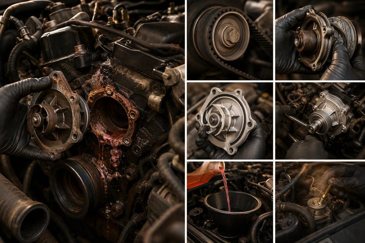
Diagnose a failed car water pump, identify its drive type, then remove, seal, torque, refill, bleed and verify the repair safely without guesswork.
Do not replace a car water pump based on overheating alone. Replace it after confirming a pump leak, bearing failure, damaged impeller or pump-specific electrical failure, then follow the service procedure for the exact year, model and engine. The drive type determines whether this is a straightforward external repair or a timing, internal-engine or electronic job best left to a specialist.
Choose the confirmed fault and pump drive; the result shows whether to replace it and how involved the job is.
Water Pump Replacement Decision
Select only what testing has established. The default result assumes overheating without a confirmed pump fault.
Overheating alone does not identify a failed water pump. Test for leaks, circulation, airflow, thermostat faults and internal engine leakage. Drive scope: — until the pump type is identified.
Drive-type boundaries
- External belt: Often the most accessible type, but it still requires the exact torque, seal and bleeding procedure.
- Timing belt: Requires preserved valve timing and any specified timing tools.
- Chain or internal: May require extensive engine disassembly.
- Electric: Confirm power, wiring and control before condemning the pump; scan-tool bleeding may be required.
Source basis: vehicle OEM procedures and the Ford, Gates and Continental guidance cited in the article. No universal torque value applies.
Confirm the Water Pump Has Failed
Work only on a cool engine. A hot cooling system is pressurized, and loosening the cap can release steam and coolant forcefully. Ford’s coolant safety guidance says not to remove the reservoir cap while the engine is hot or running.
Start with four checks:
- Locate any leak. Inspect the pump’s weep hole, the joint between the pump and engine, and nearby hose connections. Coolant leaking from above can run down and make a sound pump look faulty. If the source remains unclear, pressure-test the cold system without exceeding the pressure specified for the vehicle or cap.
- Check a belt-driven pump’s bearing. With the engine off and the belt removed, check the shaft for side-to-side movement. Gates specifies no shaft play and identifies rumbling or screeching from the pump as evidence of bearing wear in its cooling-system troubleshooting guide.
- Interpret the weep hole correctly. Ongoing drips, pronounced seepage or a large coolant trail support mechanical-seal failure. A minute amount of seepage can occur while a new pump’s seal beds in; according to the same Gates guide, it should stop after the short break-in period.
- Keep testing if overheating is the only evidence. Low coolant, a stuck thermostat, a restricted radiator, a failed cooling fan, trapped air and an internal engine leak can produce similar symptoms. This cooling-system diagnostic sequence separates leaks, airflow faults, circulation problems and possible internal engine failures.
For an electric pump, save diagnostic codes and freeze-frame data before disconnecting anything. Use the manufacturer’s circuit tests, scan-tool activation test and bleeding routine. A pump-related code does not prove the pump itself has failed; its power supply, wiring or control circuit may be responsible.
Stop if testing has not identified the failed part. A new pump will not correct a thermostat, fan, electrical-circuit or head-gasket fault.
Identify How the Pump Is Driven
Water-pump replacement describes several substantially different jobs:
- External accessory-belt pump: Often accessible after removing a belt, pulley, fan or bracket.
- Timing-belt-driven pump: Requires exact preservation of valve timing and may require dedicated timing tools. A timing error can cause major engine damage.
- Timing-chain-driven or internally mounted pump: May require extensive engine disassembly.
- Electric pump: May require scan-tool operation, circuit checks and an electronic bleeding cycle.
Obtain the OEM procedure before disassembly. Record the belt routing, timing steps, fastener locations, torque values, sealant instructions, coolant specification and bleeding method. There is no universal water-pump torque specification. For example, this 1988–1998 Chevrolet/GMC truck procedure assigns different values to the pump bolts and fan fasteners; those values do not apply to other vehicles.
A timing-drive pump is not a suitable first timing-belt job. Stop if the procedure requires timing fixtures you do not have, engine support, major disassembly or high-voltage precautions.
Gather the Model-Specific Parts and Tools
Use the pump matched to the VIN or exact engine code. A typical repair may also require:
- The new gasket or O-ring supplied for the pump
- Coolant meeting the vehicle’s exact specification and concentration
- A drain pan and sealable waste containers
- Hand tools and a calibrated torque wrench
- The specified belt-tensioner or timing tools
- A plastic gasket scraper and approved cleaner
- A pressure tester or vacuum-fill tool when required
Inspect the belt, tensioner, idlers, hoses and clamps while access is open. Replace them only when their condition, coolant contamination, the maintenance schedule or the repair procedure supports replacement.
When changing a timing belt, Continental recommends replacing the timing-belt-driven pump, tensioner and deflection pulleys together. The vehicle manufacturer’s schedule and procedure remain controlling.
Remove the Old Water Pump
The following is a general sequence. Vehicle-specific instructions determine the actual order, fastener torques and timing requirements.
- Cool and secure the vehicle. Disconnect the battery if the service procedure requires it. Follow the specified high-voltage isolation process on a hybrid or EV.
- Drain the coolant. Use the specified drain points or hose and capture the fluid. Keep coolant away from children and animals. Follow local disposal rules; Ford also directs owners to follow community standards for used coolant.
- Document the assembly. Record belt routing, bracket positions, connector locations and fastener positions before removing obstructing parts.
- Release the drive. Remove the accessory belt, or complete the specified engine-locking and timing-belt procedure. Do not improvise around valve timing.
- Disconnect hoses and wiring. Release electrical connector locks instead of pulling on wires. Coolant trapped above the drain point may escape when a hose or pump is removed.
- Remove the pump. Track the location and length of every bolt. Different-length bolts may secure brackets or enter holes of different depths.
- Compare the removed pump with the diagnosis. Look for a failed seal, rough bearing, damaged impeller or mounting-joint leak. If blades are missing or the coolant contains sludge, corrosion or sealant debris, locate the debris and clean the system before installing the new pump.
If the removed pump does not show the expected fault, reconsider the diagnosis before installing another part. The original leak may have come from a hose, thermostat housing or another component above the pump.
Prepare the Surface and Install the New Pump
Remove the old gasket material without gouging an aluminum mating surface. Keep debris out of coolant passages and bolt holes, then inspect the surface for corrosion or damage that could prevent the new seal from seating.
Install the supplied gasket or O-ring exactly as directed. Do not add RTV unless the pump manufacturer or OEM procedure requires it. Gates’ installation guidance says a supplied gasket should normally be the only seal and warns that excess sealant can enter the cooling system and damage the mechanical seal.
Start all pump fasteners by hand. Seat the pump evenly and tighten the fasteners in the specified sequence to the specified torque values. Do not use the bolts to pull a misaligned pump into place.
Restore the drive using the documented method. Set accessory-belt tension as specified. For a timing drive, complete the required hand-rotation check and verify every timing mark before cranking the engine.
Refill, Bleed and Verify the Repair
Use coolant that meets the vehicle’s written specification, not coolant selected only because its color resembles what was drained. Ford warns that mixing coolant types can damage cooling-system components, while Continental notes that different inhibitor packages may be incompatible.
Flush the system by the vehicle-specific method if the old coolant was contaminated, the wrong coolant was present or debris was found. Avoid pushing old debris through the new pump or another sensitive component.
Refill and bleed the system exactly as specified. Depending on the vehicle, that may require bleed screws, a vacuum-fill tool, an elevated reservoir or an electronic-pump routine. Trapped air can prevent circulation and cause overheating.
Do not spin a new mechanical pump dry. Gates explains that its mechanical seal requires a film of coolant and provides specific pre-wetting methods. Follow the instructions supplied with the replacement pump rather than assuming one method applies to every design.
After installation:
- Complete the prescribed bleeding routine.
- Monitor coolant temperature with a scan tool when one is available.
- Confirm cabin heat, cooling-fan operation and a stable coolant level.
- Inspect the pump joint, weep hole, hoses, drains and bleed screws for leakage.
- Let the engine cool fully, then recheck the coolant level.
- Pressure-test again if the level falls or fresh residue appears.
Do not road-test a vehicle that still overheats, loses coolant, has no heater output after warming up or develops new drive-belt noise. Stop and recheck both the repair and the original diagnosis.