
Bad MAP Sensor Signs: Test the Reading Before Buying a Sensor
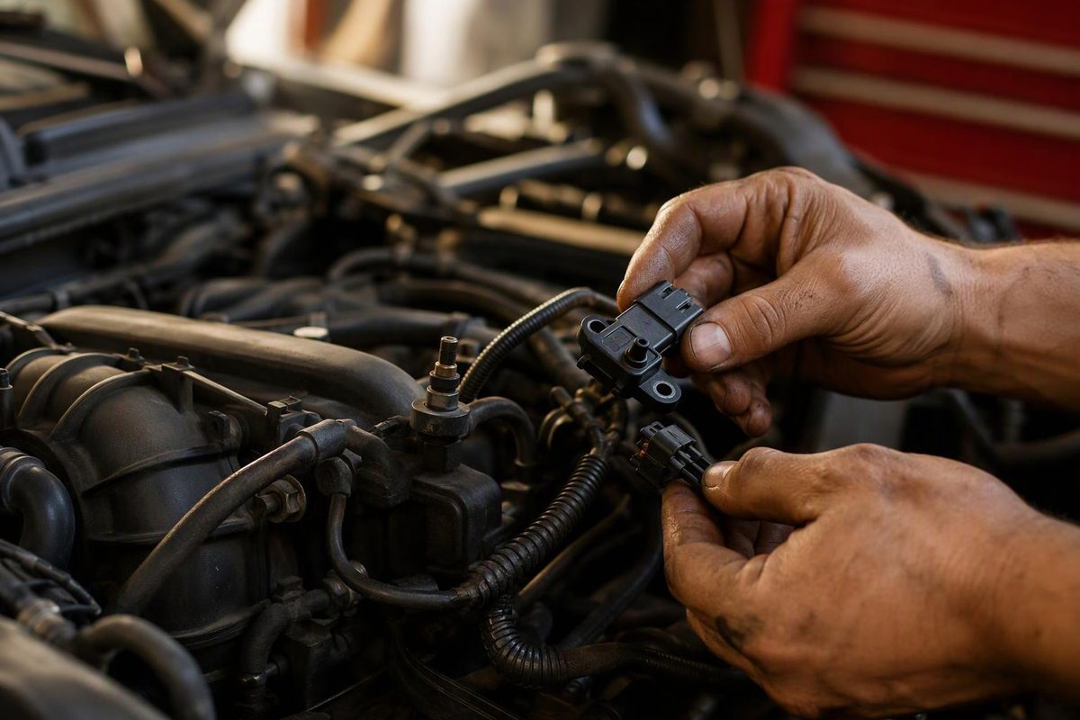
Learn the signs of a bad MAP sensor, what P0106–P0109 mean, and how scan data, pressure checks and wiring tests separate sensor failure from other faults.
Common signs of a bad MAP sensor include rough idle, hesitation, weak acceleration, stalling, increased fuel consumption and a check engine light. But those symptoms do not identify the failed part. The stronger evidence is a pressure reading that disagrees with independently measured pressure, or a signal that fails to respond correctly after circuit faults and pressure-path problems have been ruled out.
MAP means manifold absolute pressure. The engine computer uses this information to help determine engine load, fuel delivery and—in gasoline engines—ignition timing. Incorrect information can upset the air-fuel mixture, producing either rich-running or lean-running symptoms. Delphi’s MAP sensor guide describes both patterns and recommends testing before replacement.
Signs worth investigating
| What you notice | What it tells you—and what it does not |
|---|---|
| Rough or unstable idle | Incorrect fueling is possible, but the symptom does not distinguish a MAP fault from an intake leak, ignition problem or other engine fault. |
| Hesitation, surging or weak acceleration | Load information may be wrong. Record whether it happens cold, warm, at light throttle or under heavy load. |
| Stalling | A MAP-related mixture problem is possible; repeated stalling makes continued driving unsafe. |
| Poor fuel economy or a gasoline smell in the exhaust | Rich operation is possible. This does not prove the sensor caused it. A suspected fuel leak needs immediate attention. |
| Check engine light, even with normal drivability | The computer may have detected an electrical or pressure-plausibility fault before obvious running problems appear. |
These running symptoms are consistent with the warning signs listed by Delphi. They are reasons to investigate, not a replacement checklist.
Stop road-testing if the engine repeatedly stalls, loses power dangerously or runs with a flashing check engine light. See the guidance on what a flashing check engine light means.
What MAP-related codes actually mean
Common generic codes include:
- P0105: MAP/barometric-pressure circuit malfunction.
- P0106: MAP/barometric-pressure range or performance problem.
- P0107: Circuit low input.
- P0108: Circuit high input.
- P0109: Intermittent circuit fault.
Correlation codes such as P0068 or P0069 can also involve MAP information. These identify the type of fault the computer detected, not necessarily its cause. Low or high input refers to the electrical signal; it is not automatically proof of low or high manifold pressure. Delphi explicitly notes that other sensors or faulty parts can set MAP-associated codes.
Test in this order
1. Save the conditions, then inspect the pressure path
Before clearing anything, record stored and pending codes and freeze-frame data. Note RPM, throttle position, MAP pressure and whether the engine was cold or warm. This gives you conditions to reproduce after a repair. Toyota’s 1KD-FTV diagnostic procedure, applicable from August 2004, specifically calls for reading freeze-frame data to establish the conditions when the fault occurred.
Identify the correct sensor using service information for the exact model year and engine. Some engines combine pressure and intake-air temperature in a TMAP sensor; connector pin count alone is not enough to select a test.
With the ignition off, inspect:
- The connector lock, terminals and nearby harness for looseness, corrosion, rubbing or heat damage.
- Any hose connecting the sensor to the manifold for splits, kinks, loose connections or blockage.
- The sensor’s pressure opening and mounting seal, where accessible.
A blocked hose can prevent a good sensor from seeing pressure changes; a leaking hose can give it the wrong pressure. These are documented failure paths in Delphi’s troubleshooting procedure.
Stop point: Repair visible connector, hose or sealing defects, then repeat the checks before buying a sensor.
2. Check key-on, engine-off pressure
Use a scan tool that displays live MAP data. With the engine stopped and manifold pressure allowed to equalize, turn the ignition on without starting it. The MAP reading should be close to actual local atmospheric pressure. This comparison is also the initial scan-data check in Toyota’s 1KD-FTV procedure; use your vehicle’s specified tolerance to judge the result.
Compare it with an independent pressure measurement or the manufacturer’s altitude-based specification. Do not automatically demand 100 kPa everywhere: atmospheric pressure varies with elevation and weather. Also, a matching scan-tool BARO value is not always independent confirmation—some systems derive BARO from the MAP sensor at key-on, as Delphi explains.
MAP is absolute pressure, not vacuum or boost relative to the surrounding air. Keep units and reference points consistent when comparing readings.
3. Check response—and separate bad data from real pressure
On a conventional throttled gasoline engine, starting the engine should lower manifold pressure below the engine-off reading. Opening the throttle normally raises pressure toward atmospheric pressure, as described in Delphi’s operating explanation. Boost can raise it above atmospheric pressure. Do not apply a gasoline idle expectation to a diesel engine—use that engine’s specified conditions.
Watch whether MAP responds consistently as operating conditions change. A flat, erratic or implausible reading warrants further testing, but a smooth response does not rule out an offset reading.
Where service information permits, compare scan data with a separate manifold pressure/vacuum gauge. Auto Dynamics’ MAP diagnostic article illustrates the distinction between absolute-pressure scan data and a vacuum-gauge reading. For example, if atmospheric pressure is 100 kPa and measured vacuum is 60 kPa below atmosphere, the corresponding MAP is 40 kPa absolute. This is a conversion example, not a universal idle specification.
Stop point: If MAP agrees with independently measured pressure, investigate why the engine’s actual pressure or running condition is abnormal rather than condemning the sensor.
4. Verify the circuit, then test against known pressure
For a typical three-wire analog sensor, use the wiring diagram to identify reference supply, sensor ground and signal. Check the supply and ground before interpreting the signal. Many use a nominal 5-volt reference, but the exact limits and pin assignments must come from vehicle service information.
If the procedure permits, leave the sensor electrically connected and apply controlled vacuum with a hand pump. Compare the signal at several known pressure points with the specified pressure-to-output chart. It should track the chart smoothly and repeatably. Some older MAP sensors output frequency rather than a varying DC voltage, so a voltage-only test is inappropriate. Fluke’s testing guide covers both output types and emphasizes verifying power and ground first.
Make back-probe connections with the engine off, avoid shorting adjacent terminals, and stay within the sensor’s rated pressure range. For running tests, work outdoors or with proper exhaust extraction and keep leads and hands clear of belts and fans. If you cannot identify the terminals or obtain the correct chart, stop at inspection and scan-data checks.
When replacement is justified
Replacement is supported when the pressure path is clear, supply and ground pass their checks, the signal circuit has no fault affecting the output, and the sensor fails the specified test at known pressure points. A shorted signal wire can invalidate an otherwise useful output test. Toyota’s diagnostic sequence includes harness checks rather than treating an abnormal signal alone as proof of sensor failure.
If the output is correct at the sensor but the scan reading is wrong, investigate the signal circuit and control-module input instead.
Do not treat cleaning as a universal cure. Follow an application-specific procedure if contamination is found; do not scrape the sensing element or assume an arbitrary solvent is safe.
After repair, repeat the engine-off pressure comparison and the operating conditions that produced the original fault. Confirm that the symptoms are gone and relevant codes do not return—not merely that the warning light has been cleared.